|
Thanks to
all our customers for taking the time to send us their pictures. If you
would care to send us a photo of your DRO installation and ultimately
benefit others who may be contemplating the same install, please send
your photos to scott@dropros.com.
Thank you!
DRO PROS carries magnetic scale kits that can't be contaminated! Call us
for all your digital readout needs!
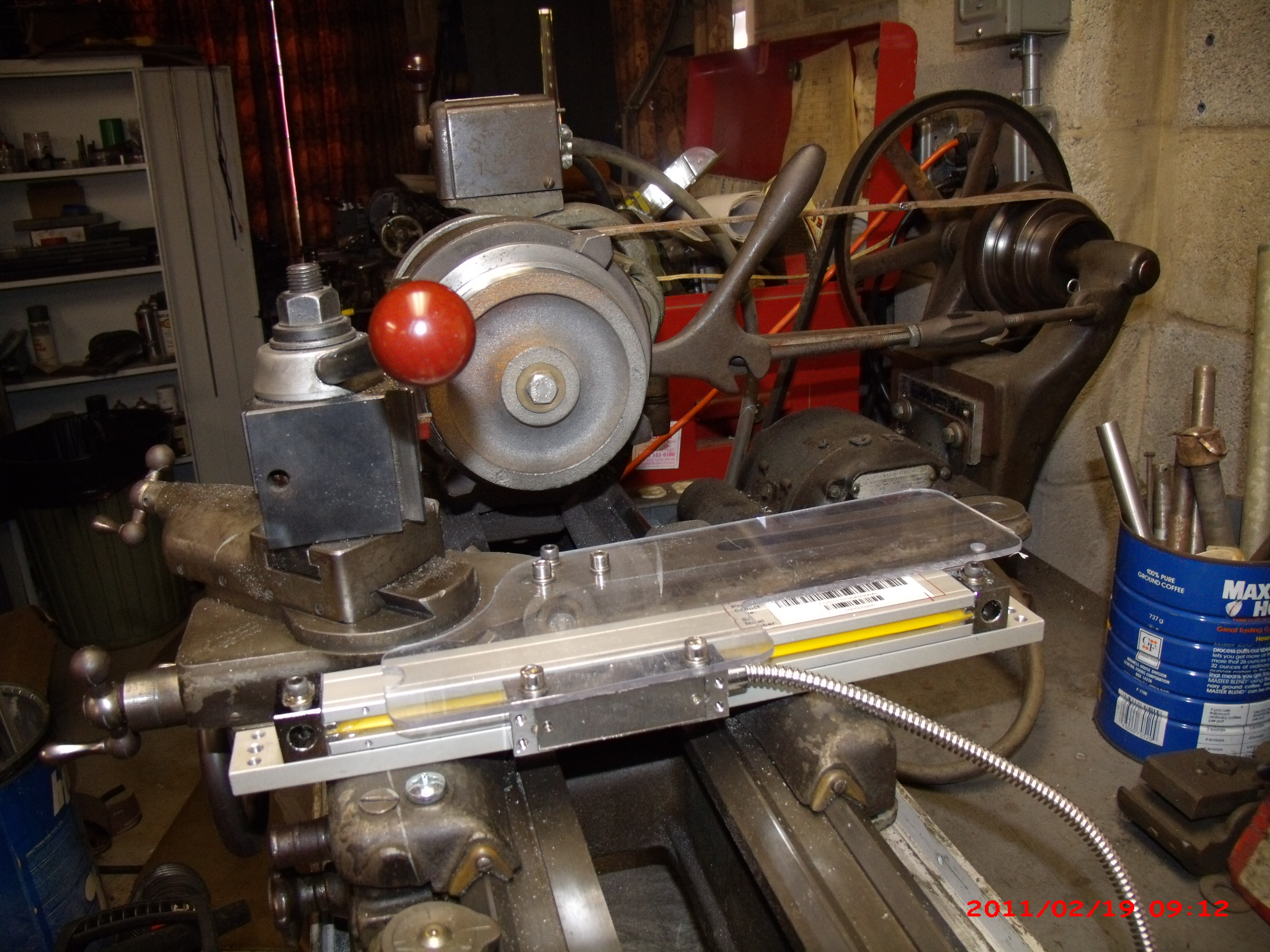
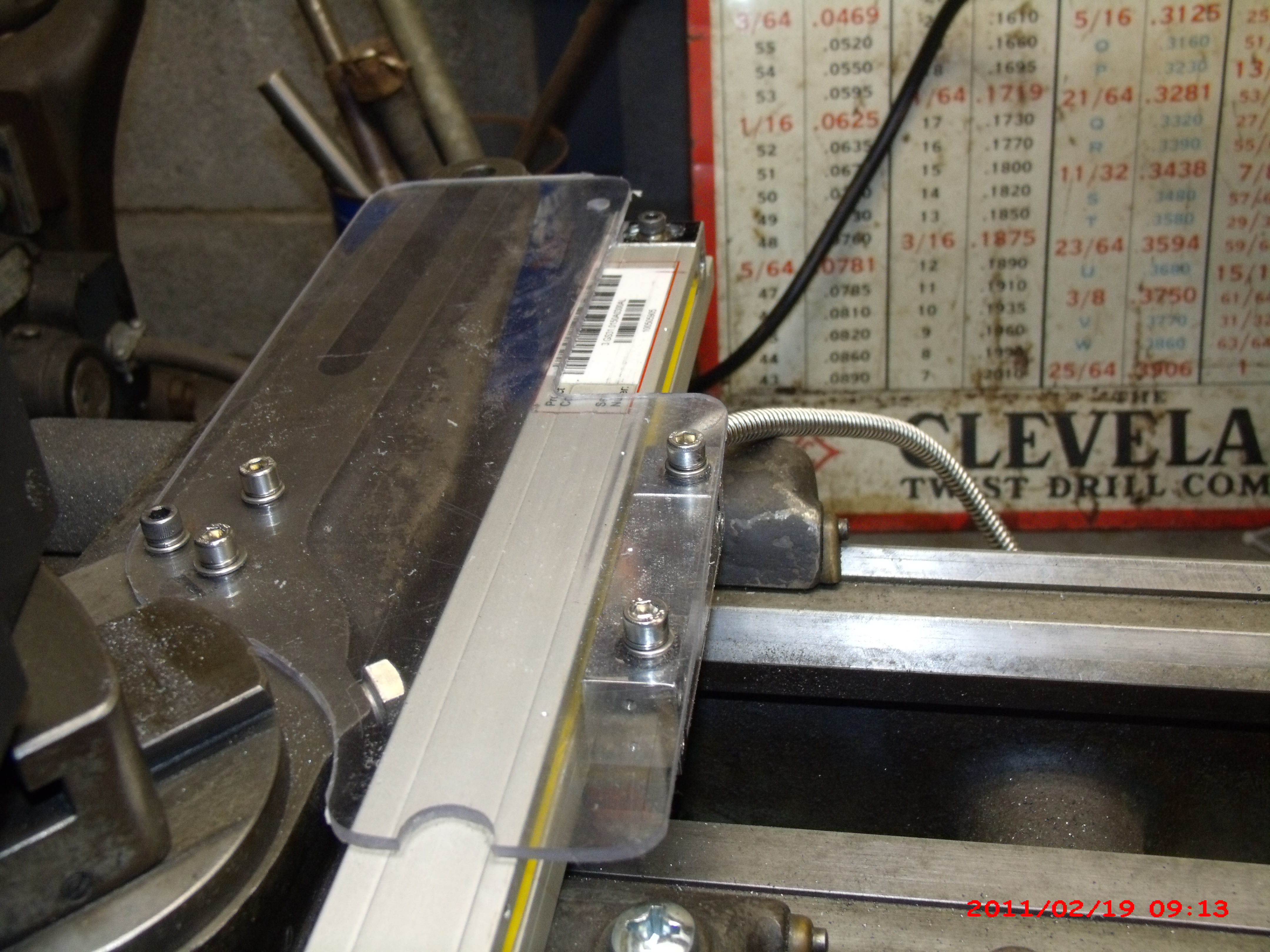
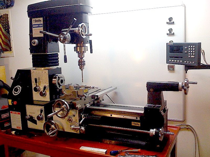
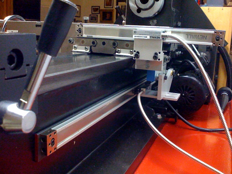
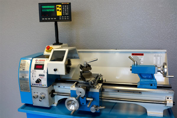
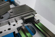
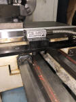
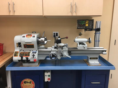
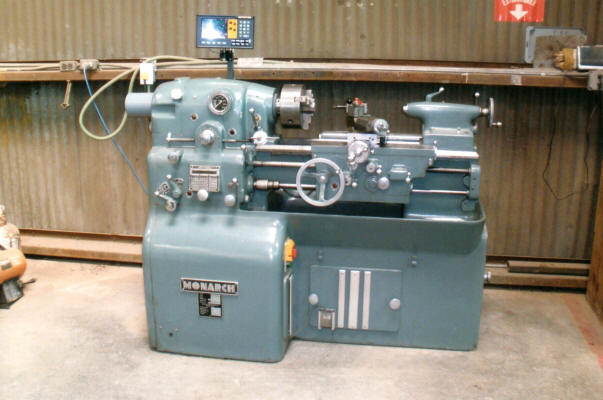
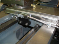
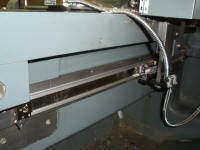
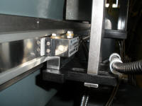
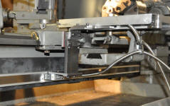
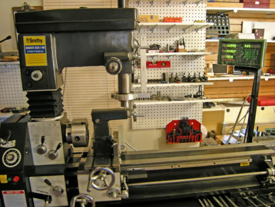
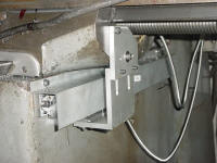
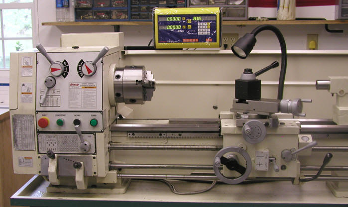
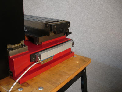
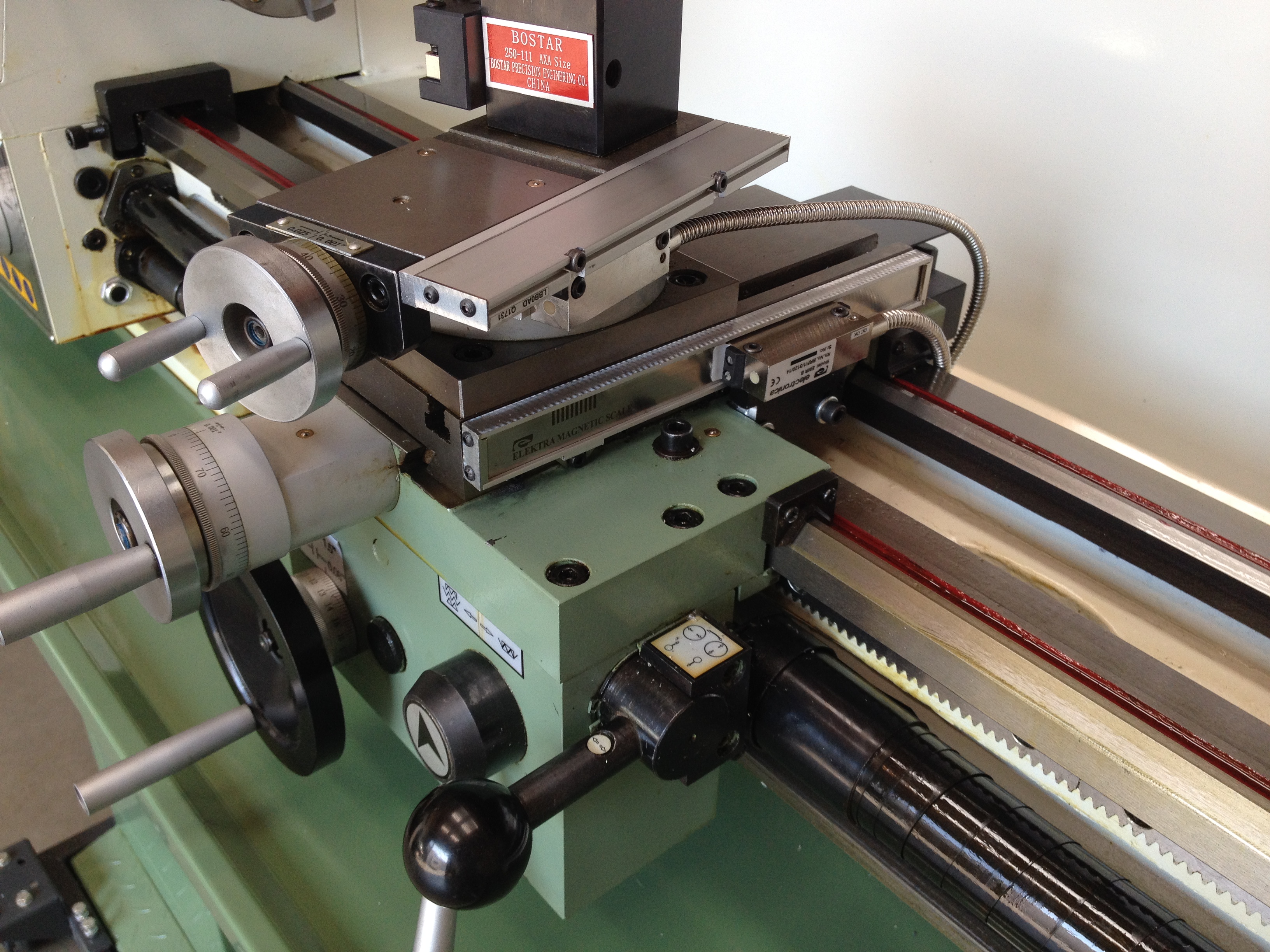
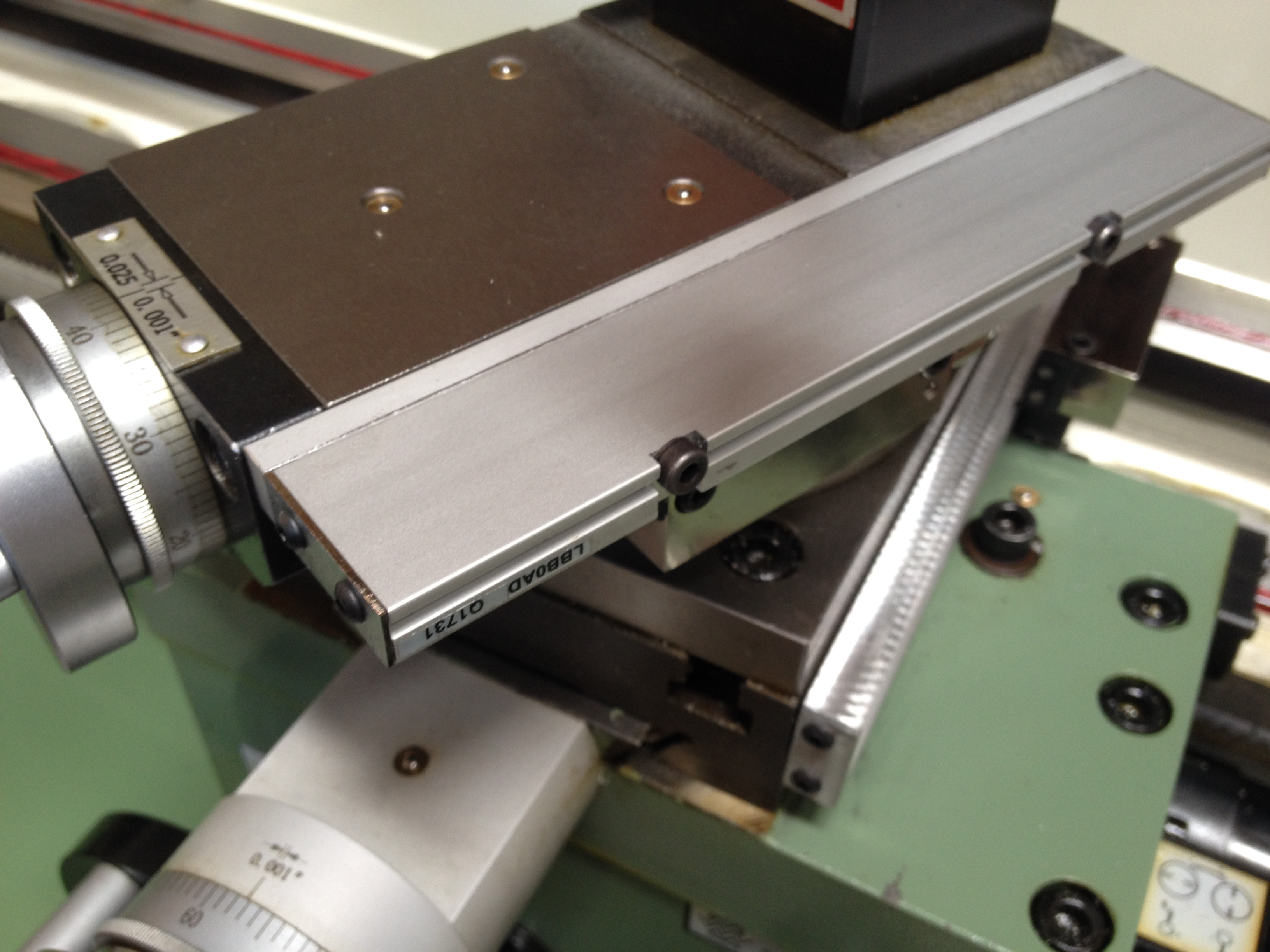
#1 - Courtesy
of T. Scholey with the new MagnaSlim Magnetic Scale
Lathe Kit:
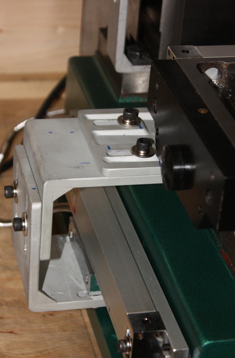
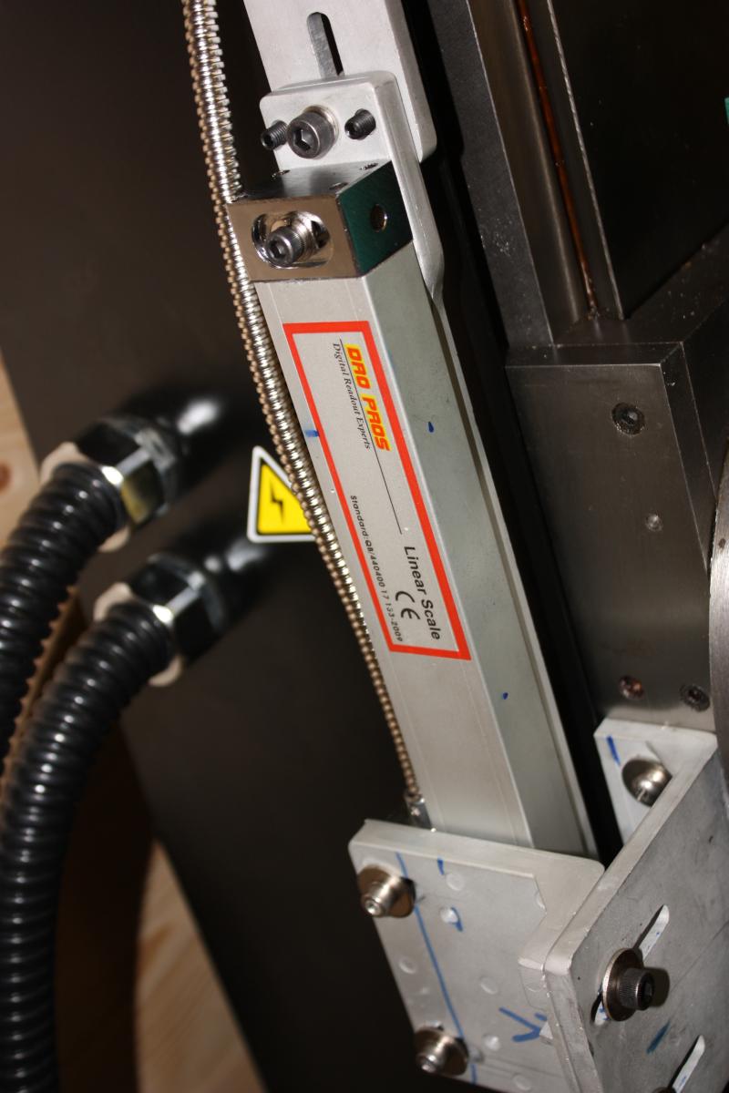
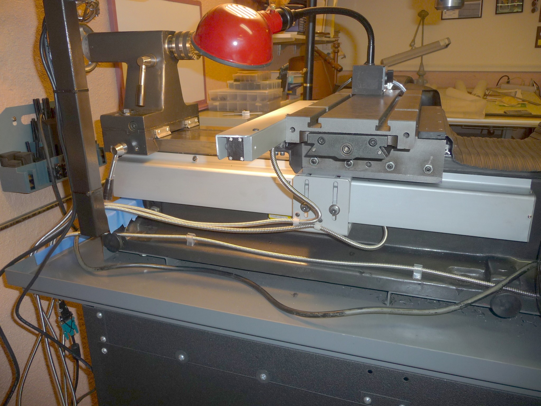
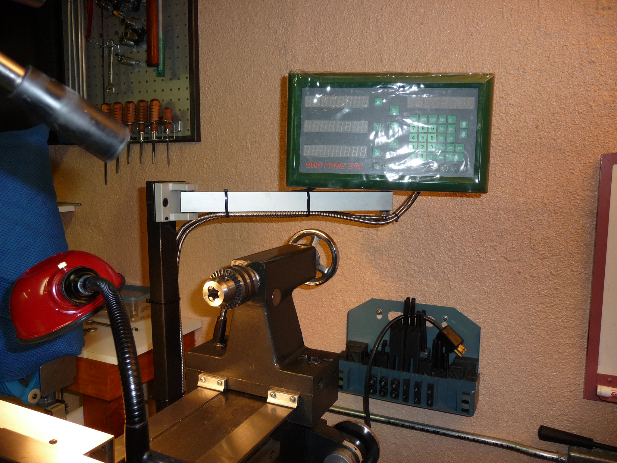
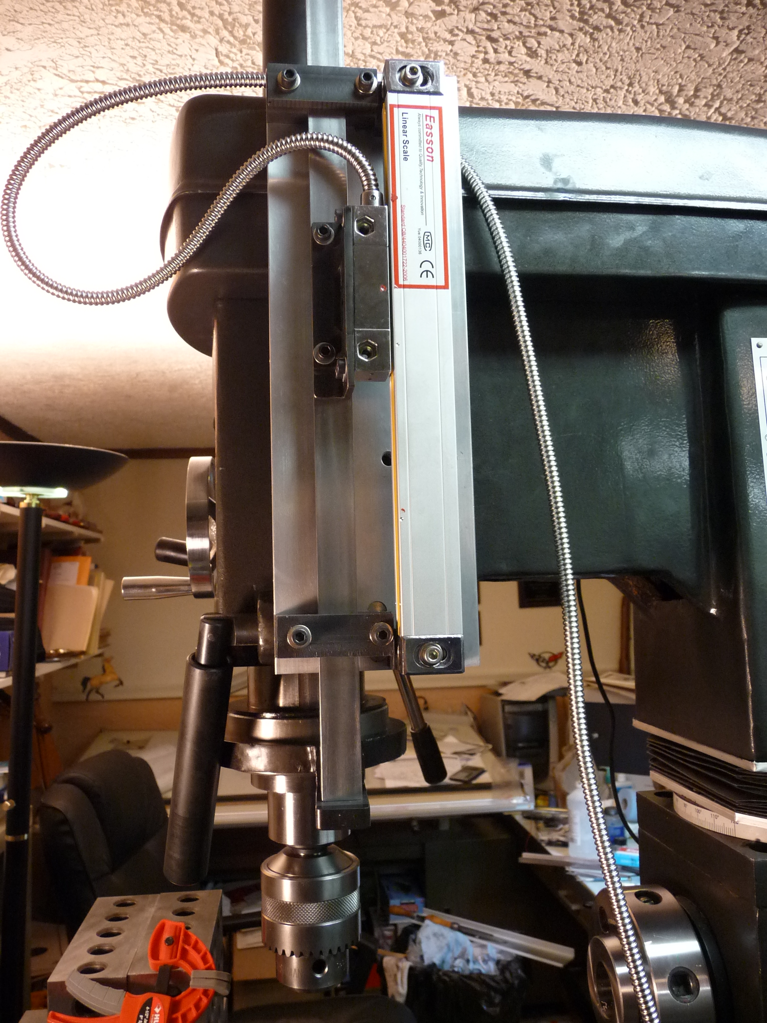
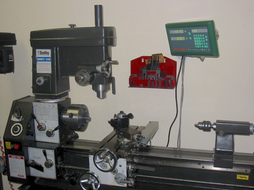
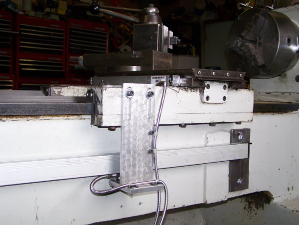
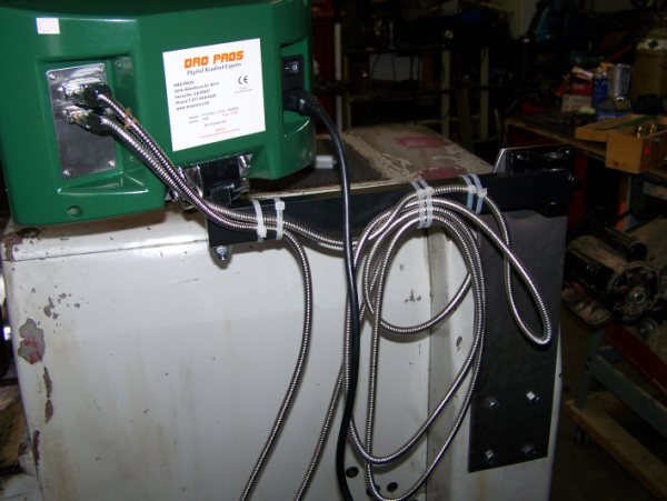
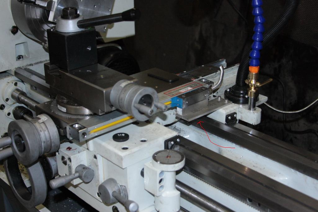
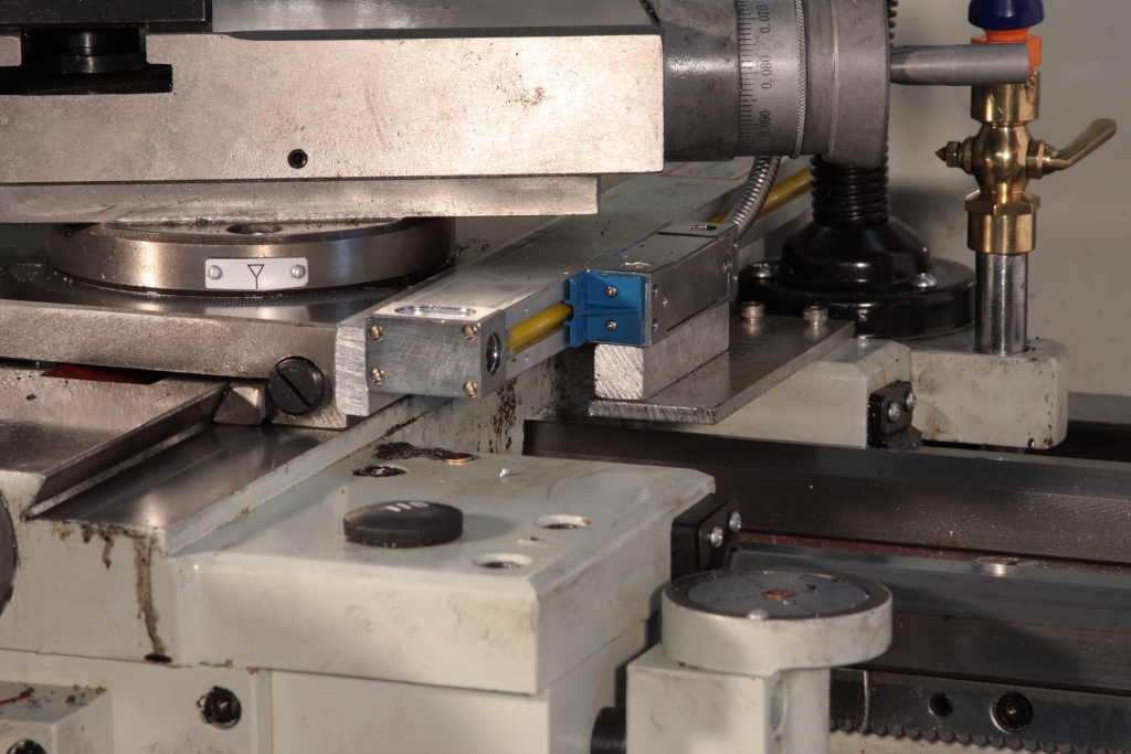
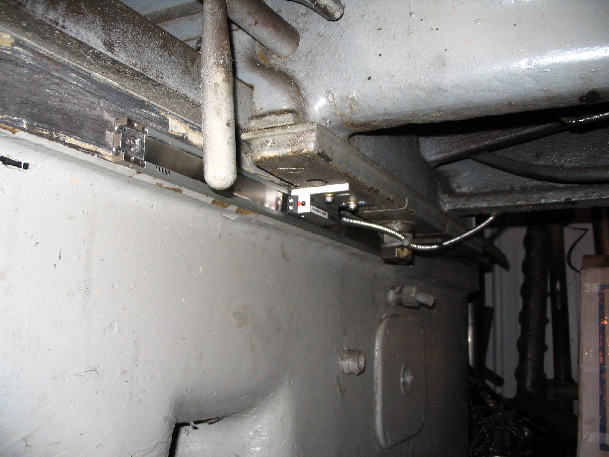
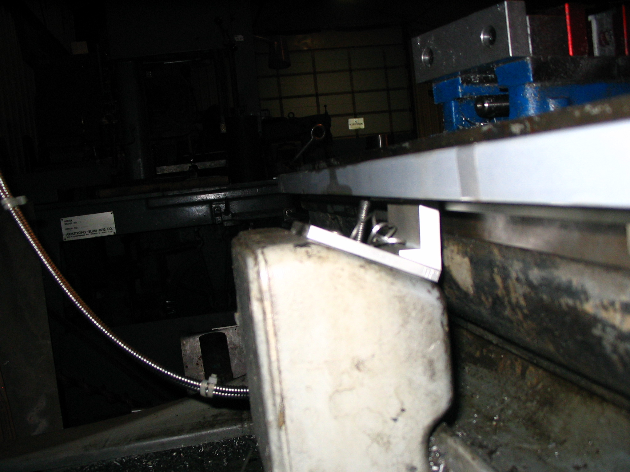
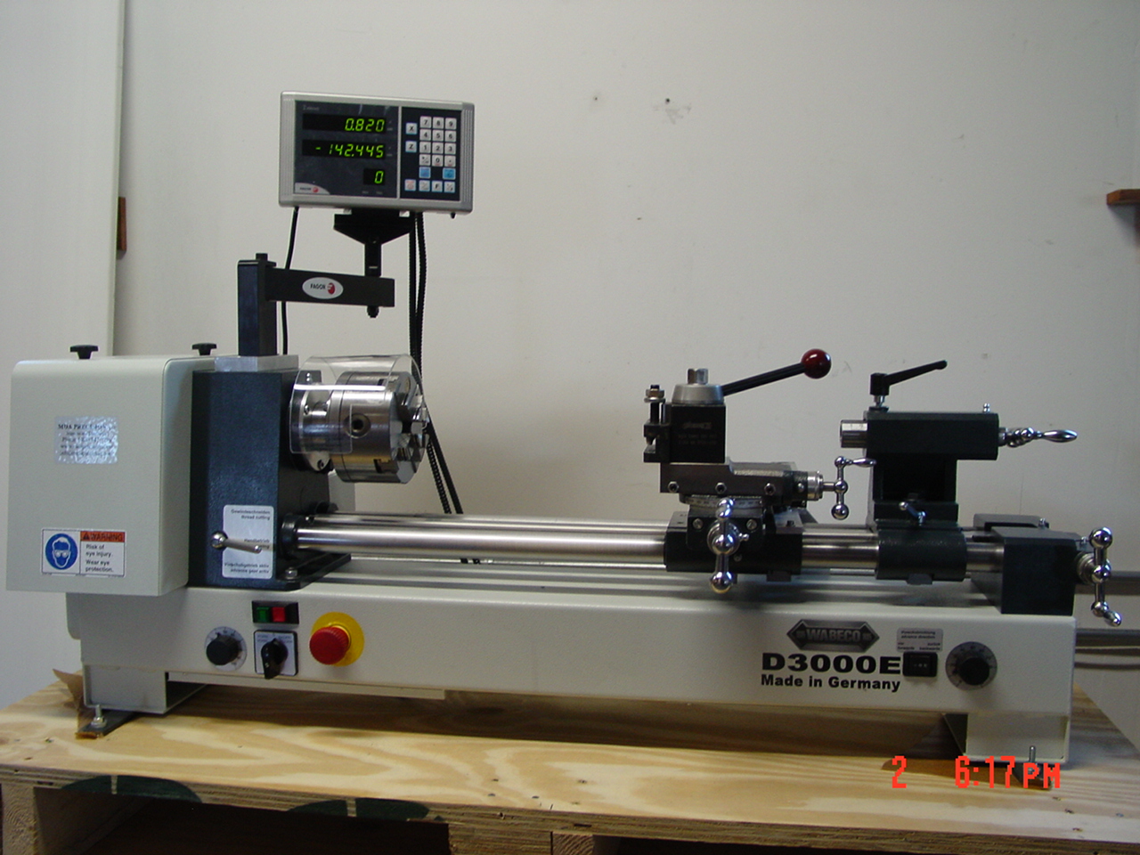
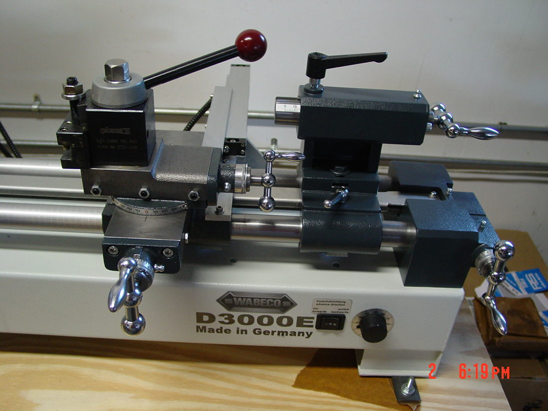
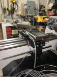
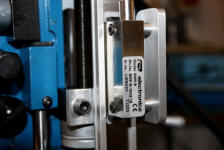
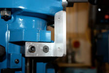
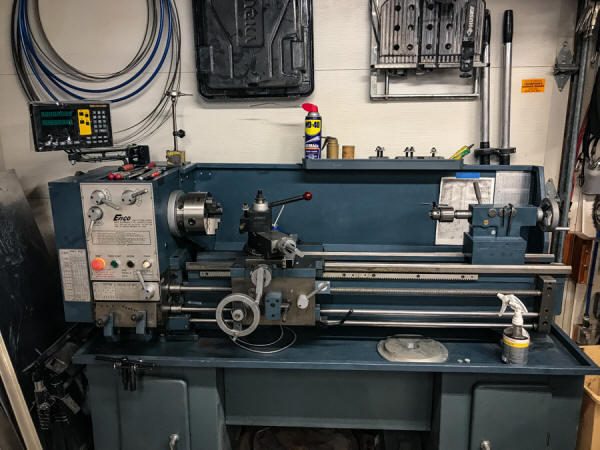
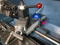
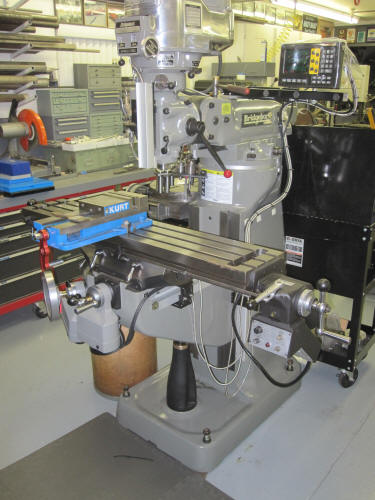
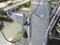
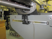
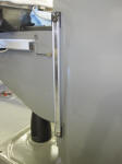
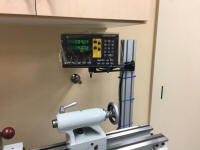
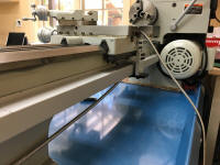
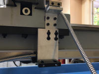
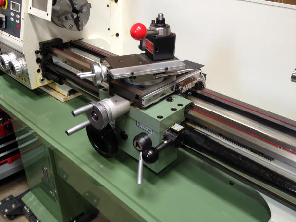
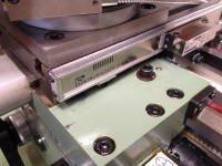
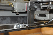
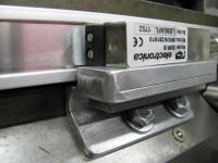
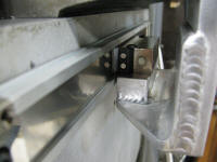
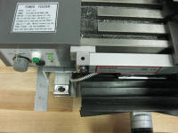
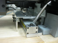
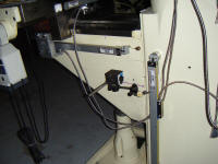
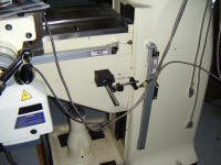
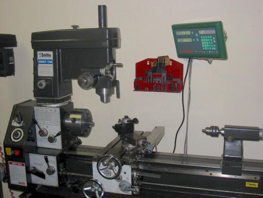
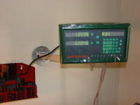
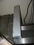
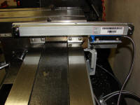
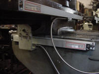
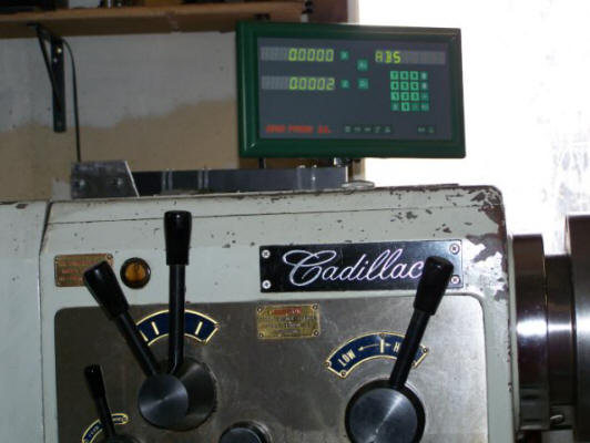
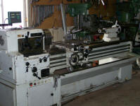
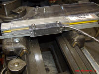
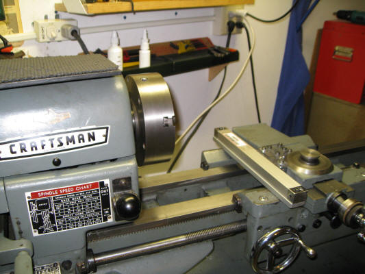
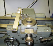
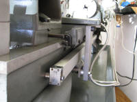
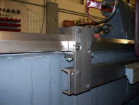
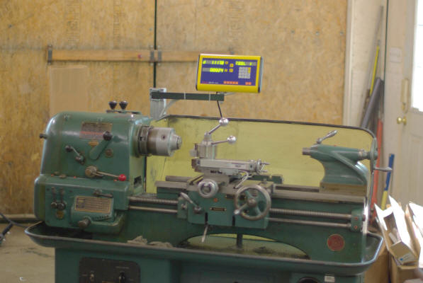
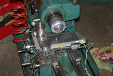
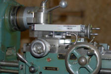
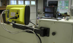
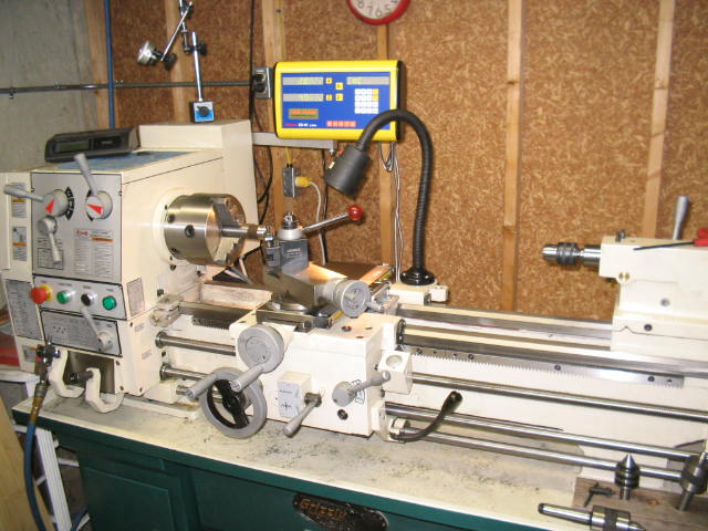
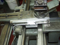
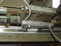
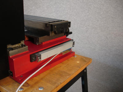
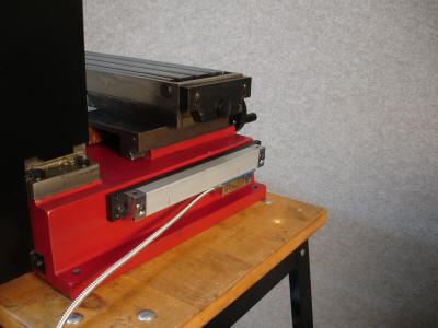
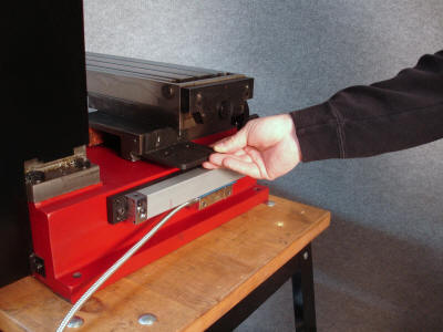
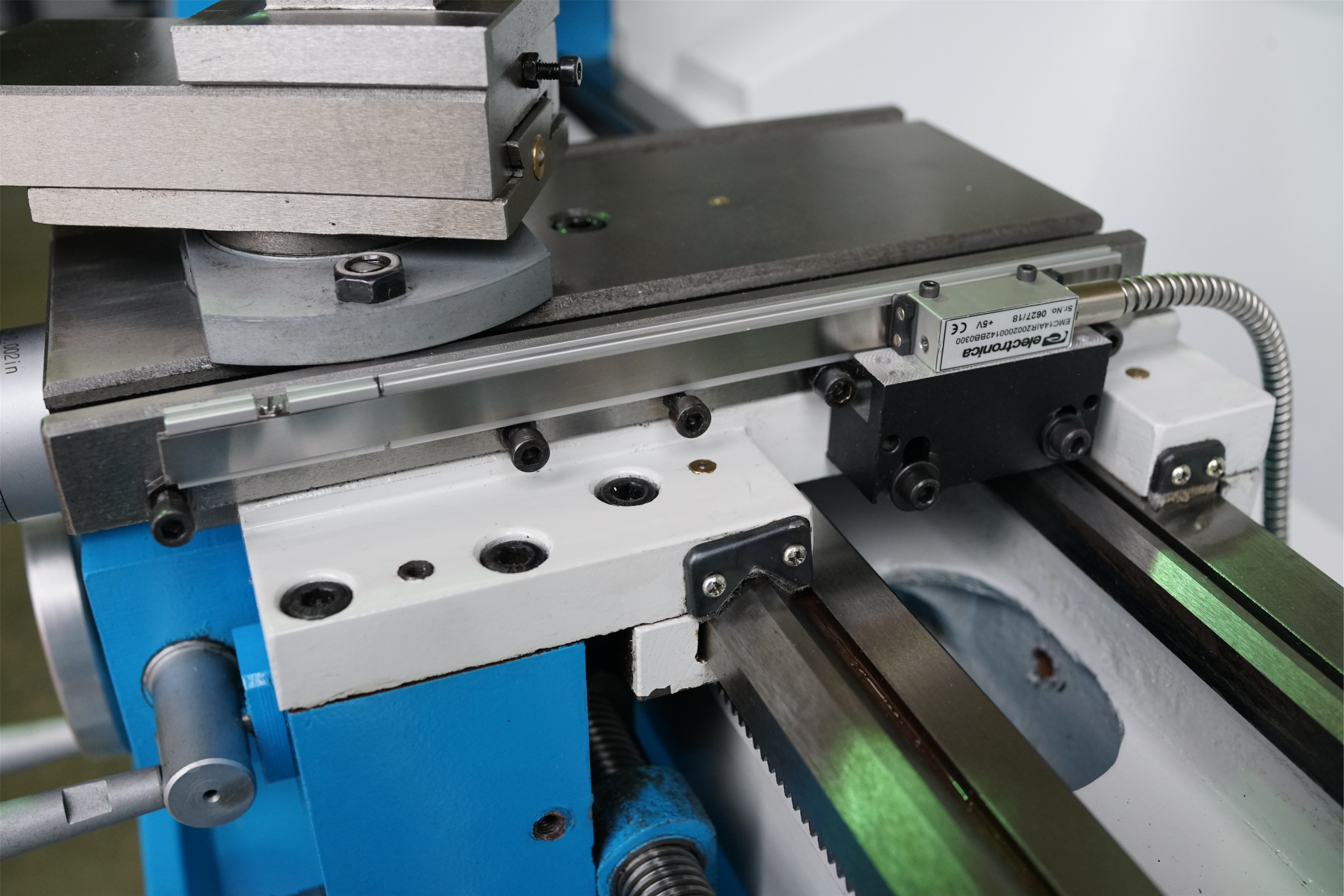
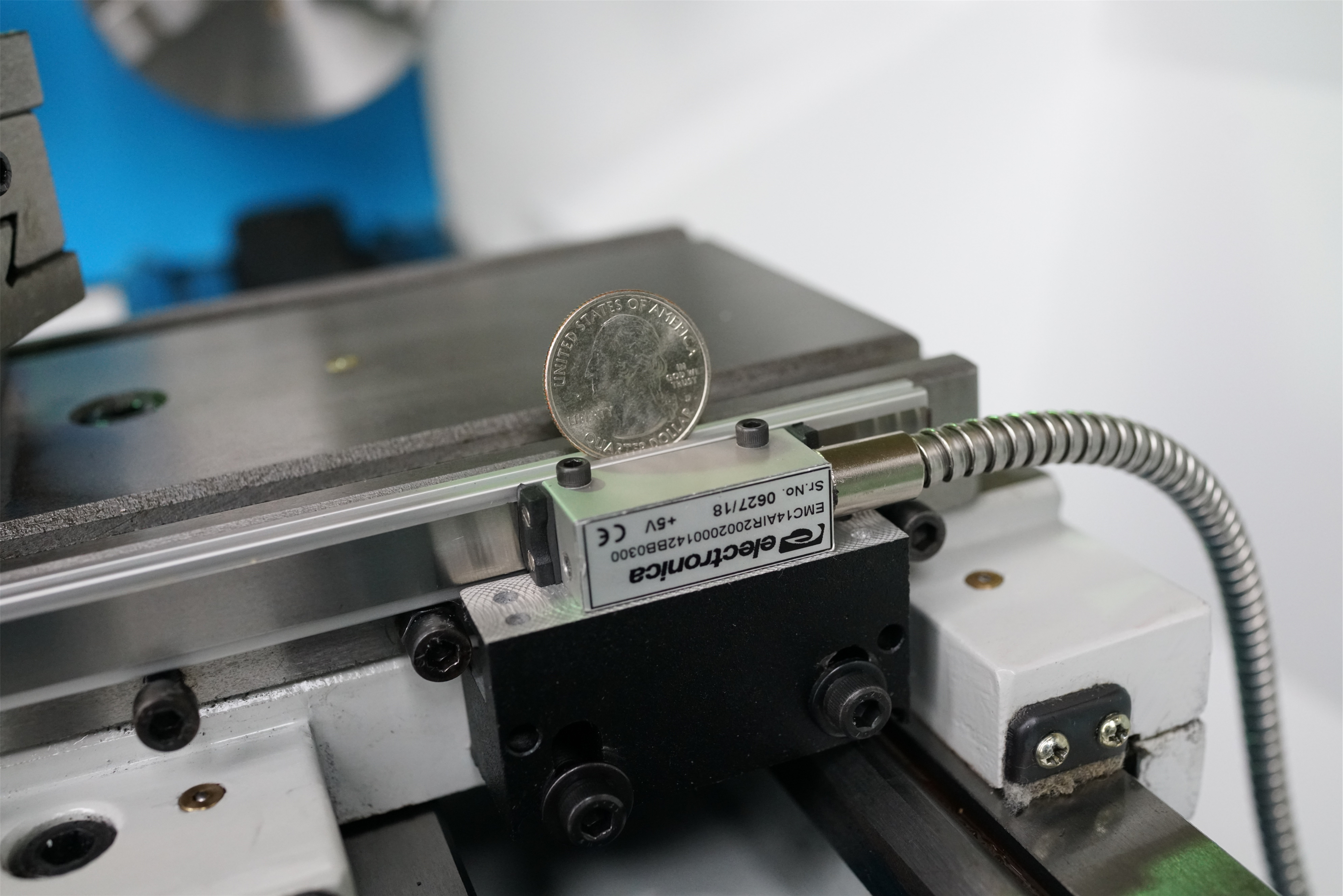
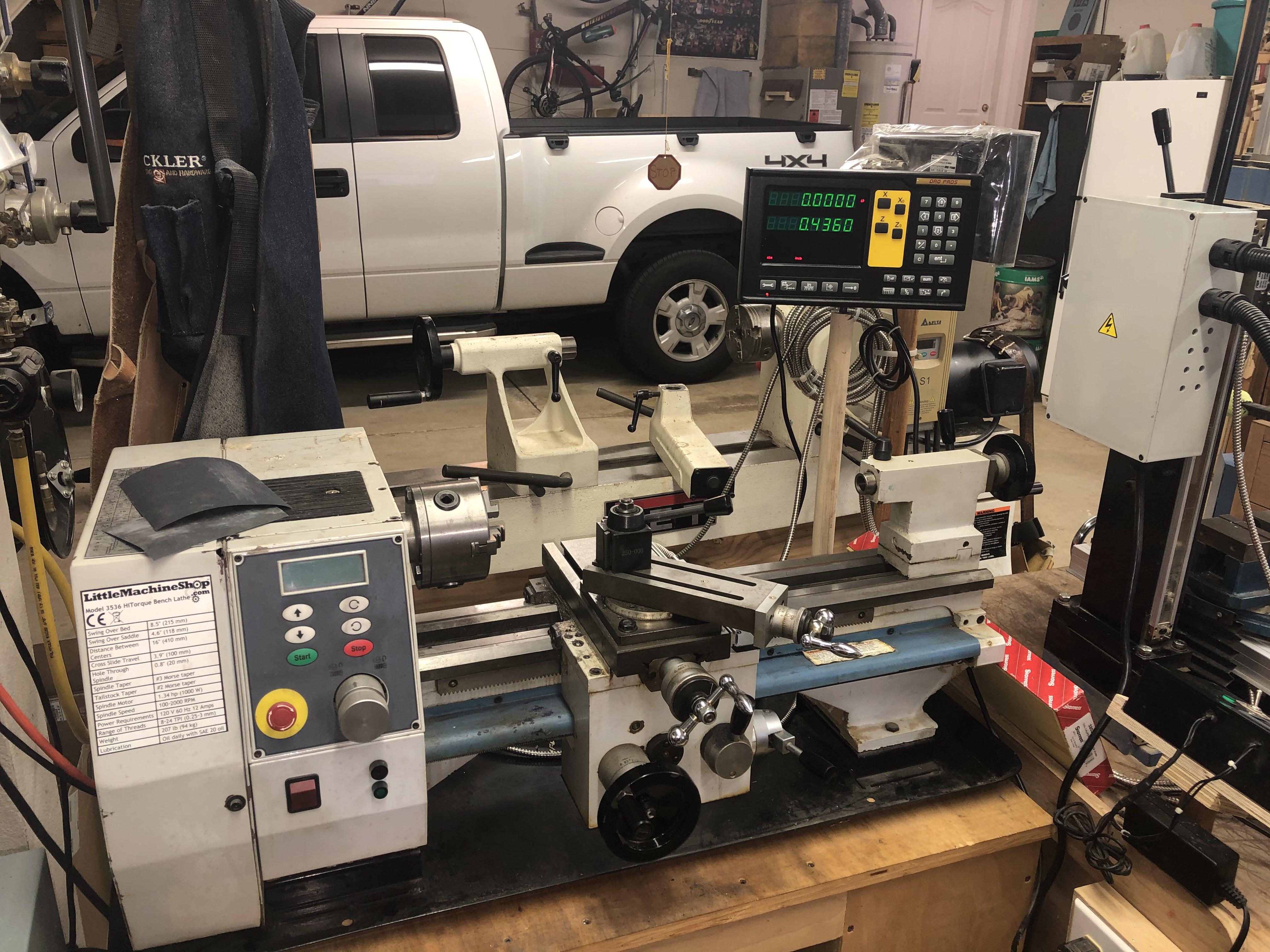
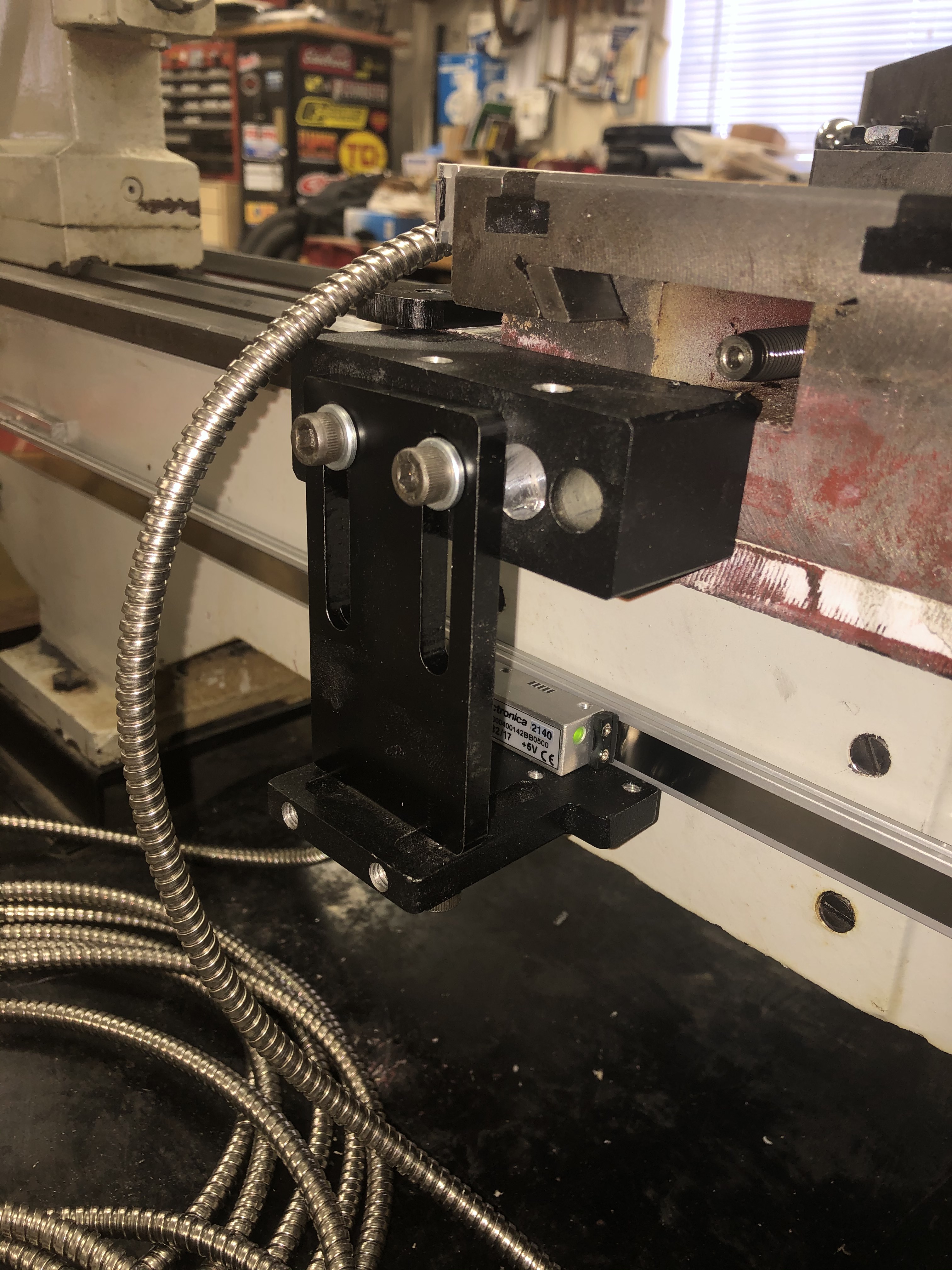
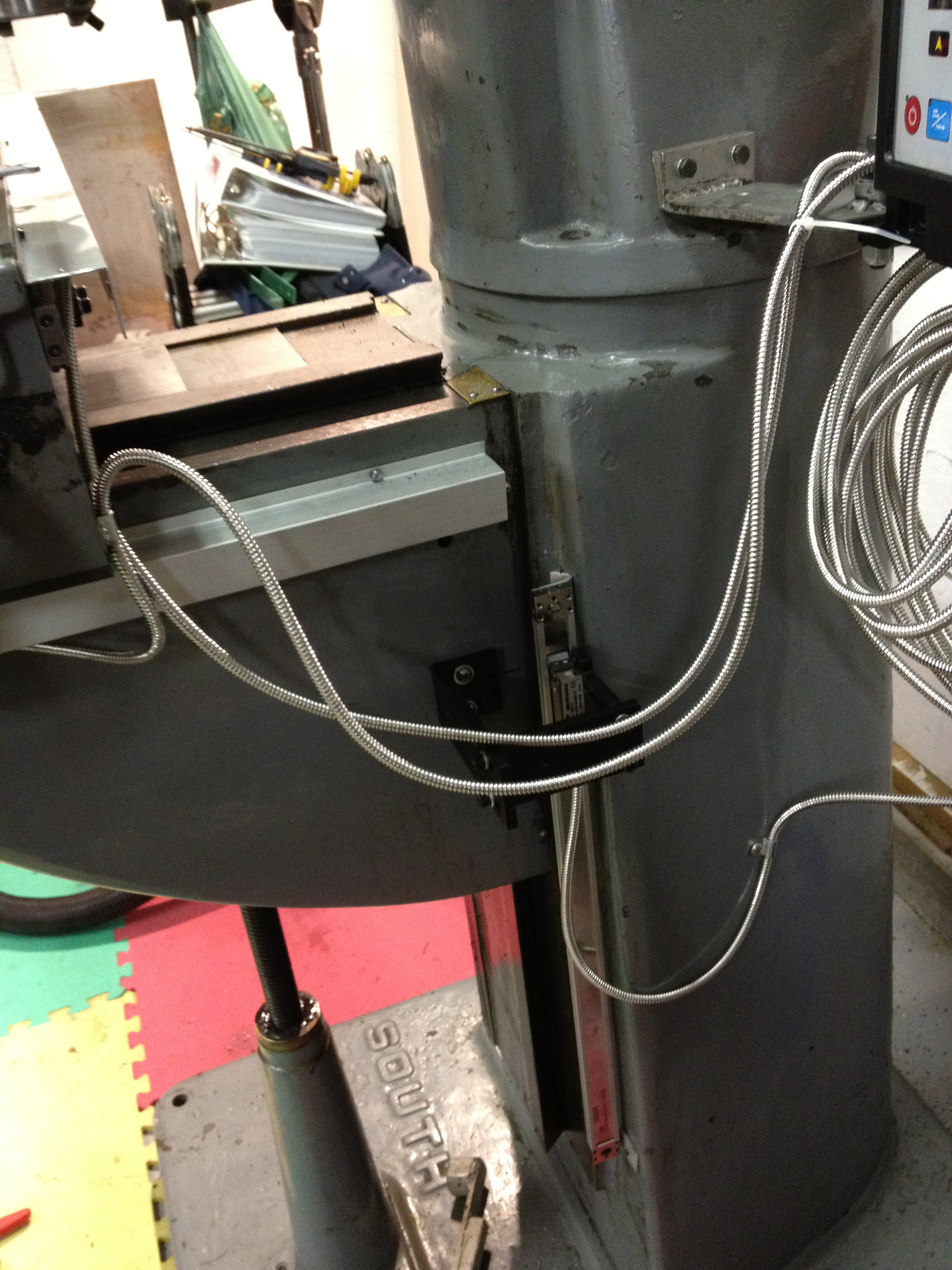
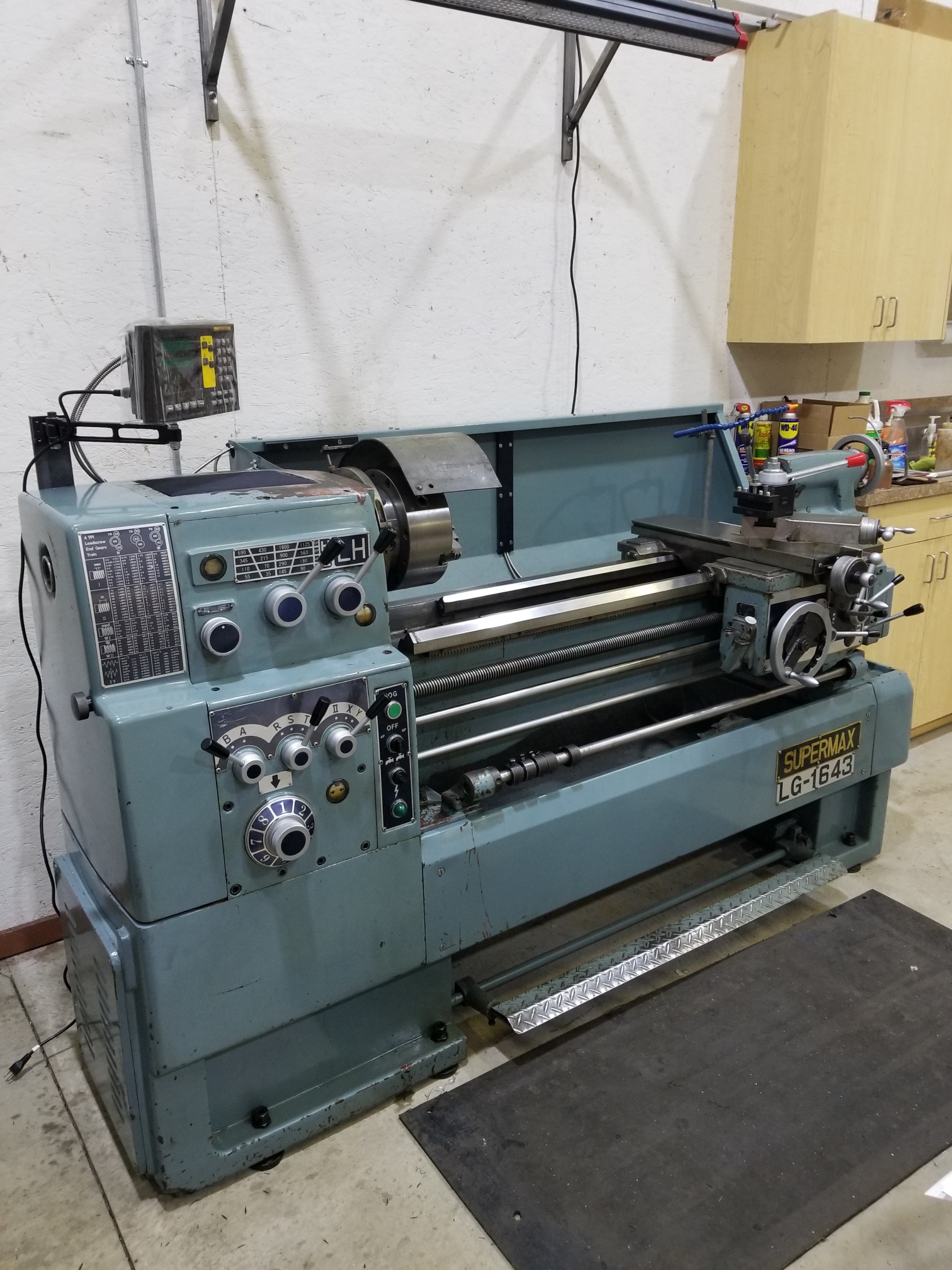
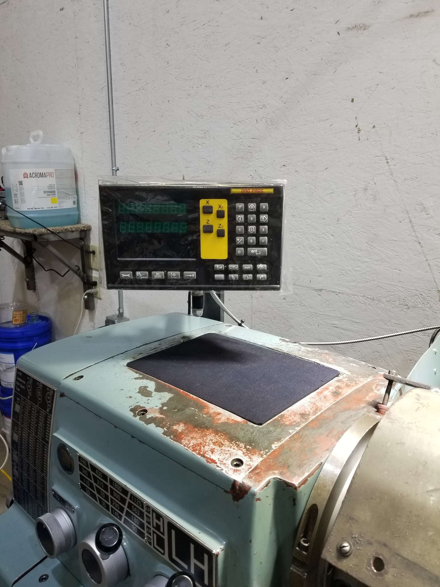
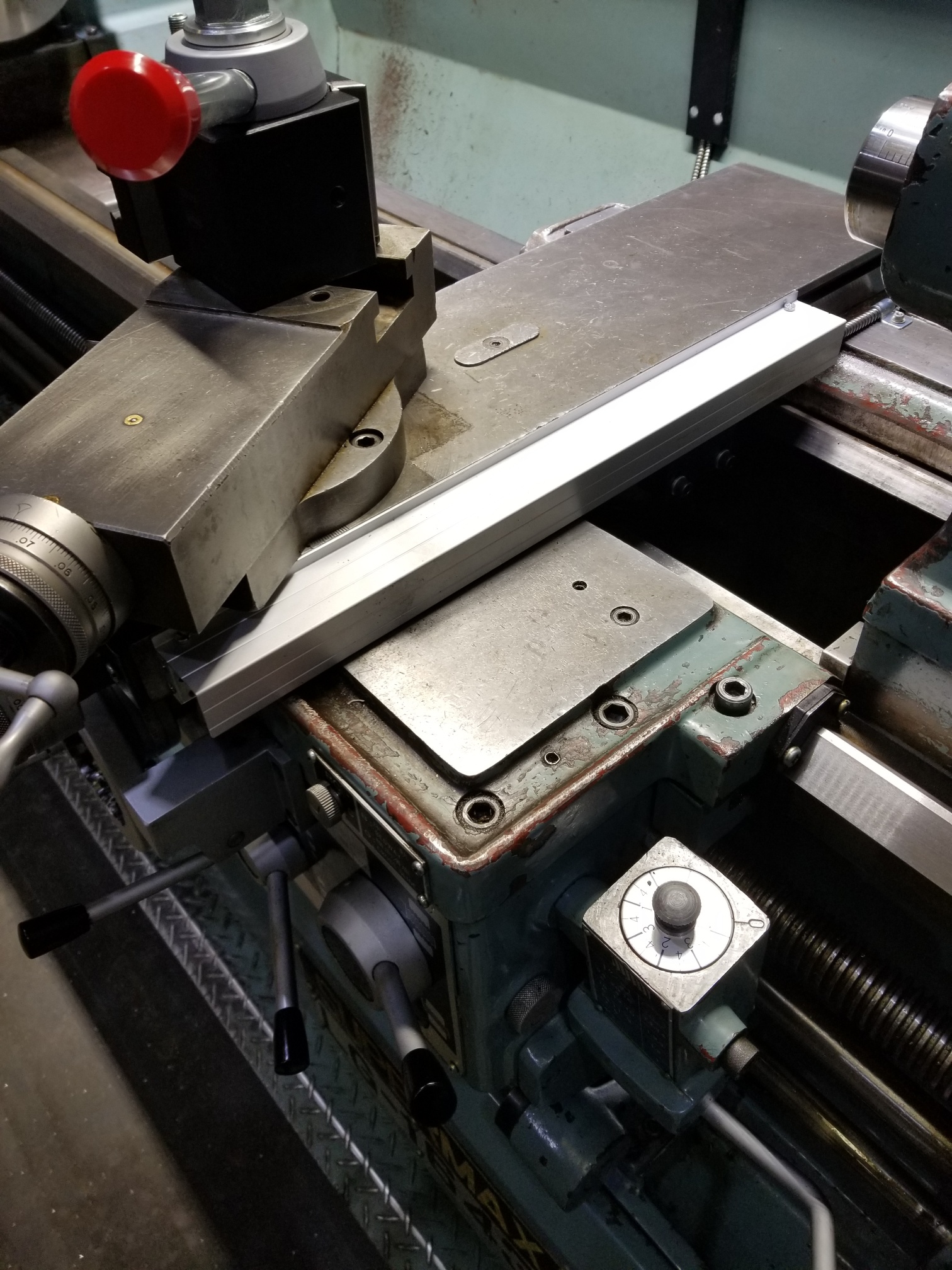
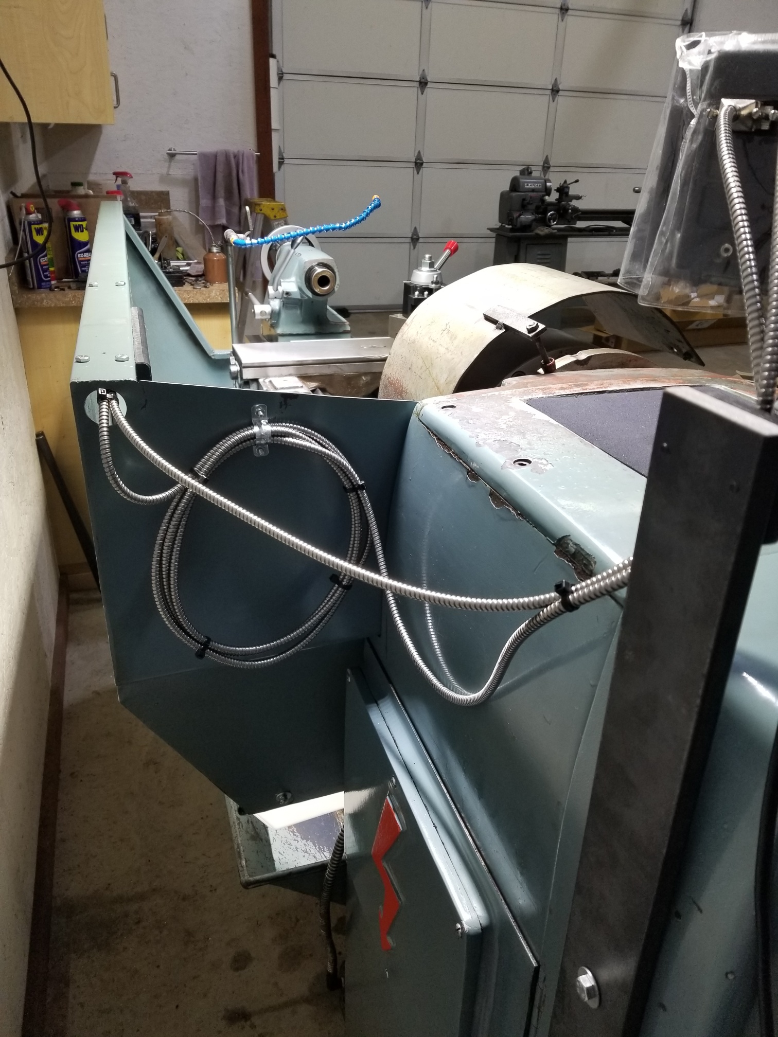
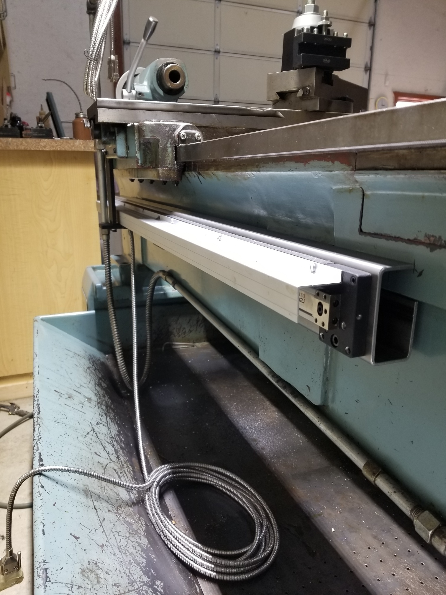
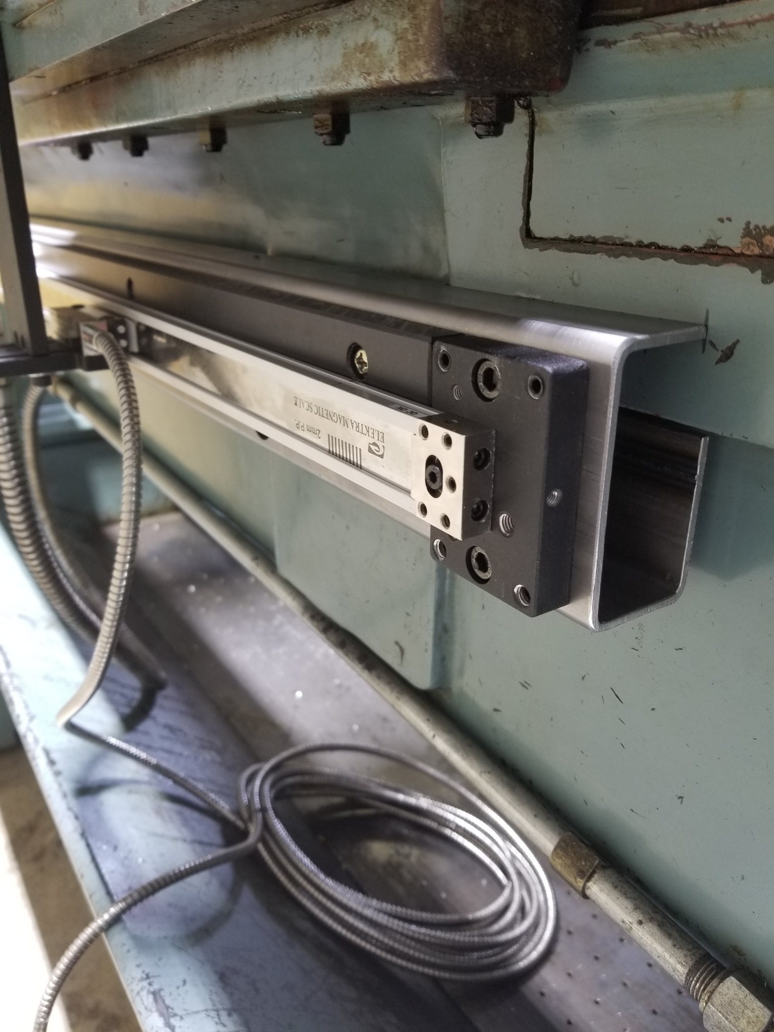
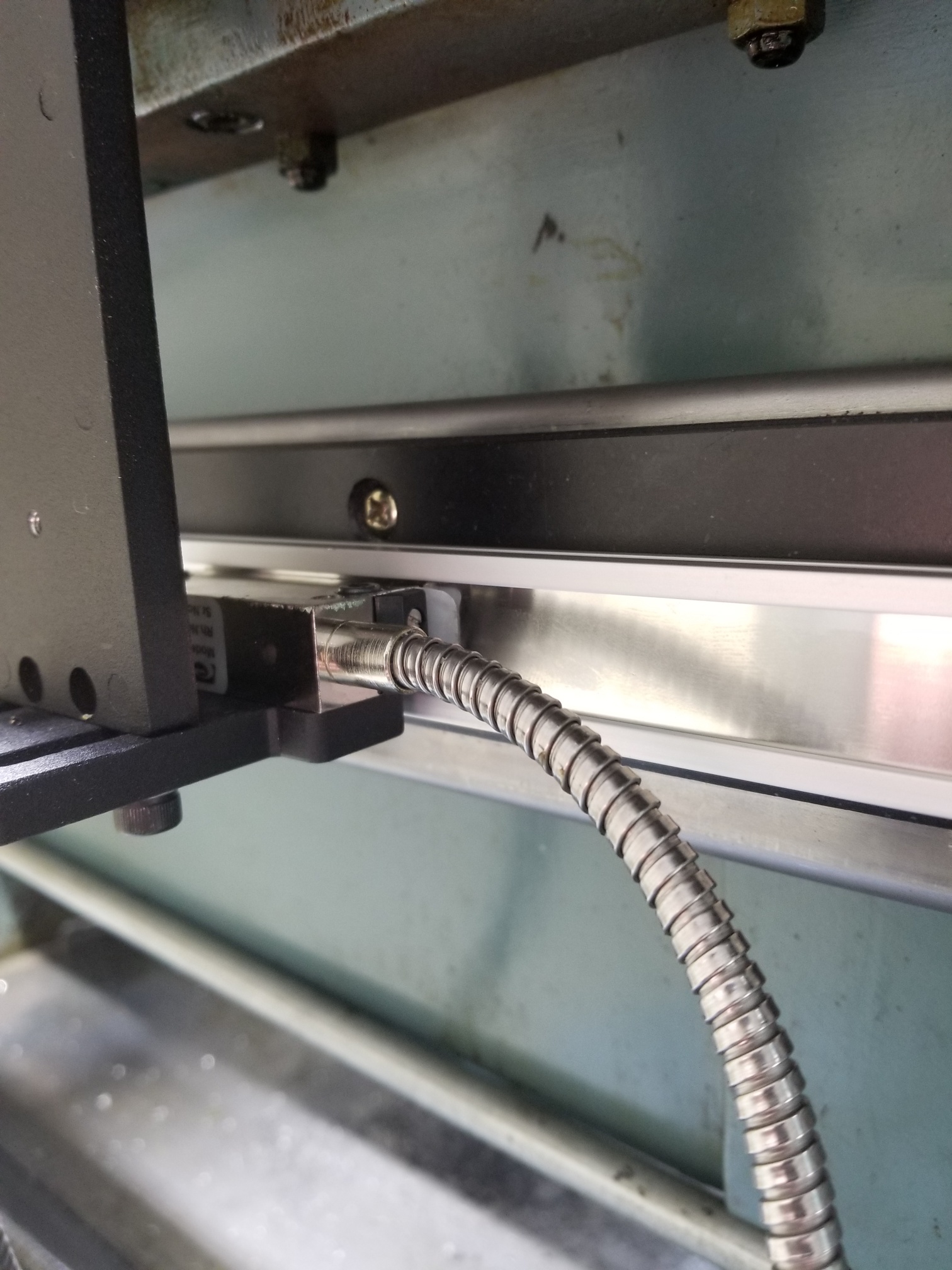
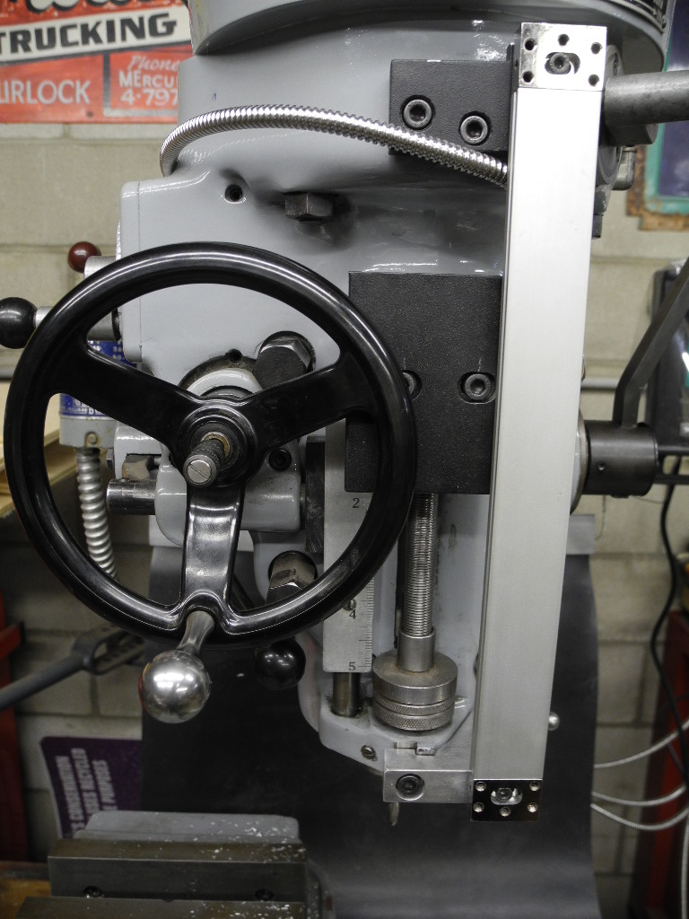
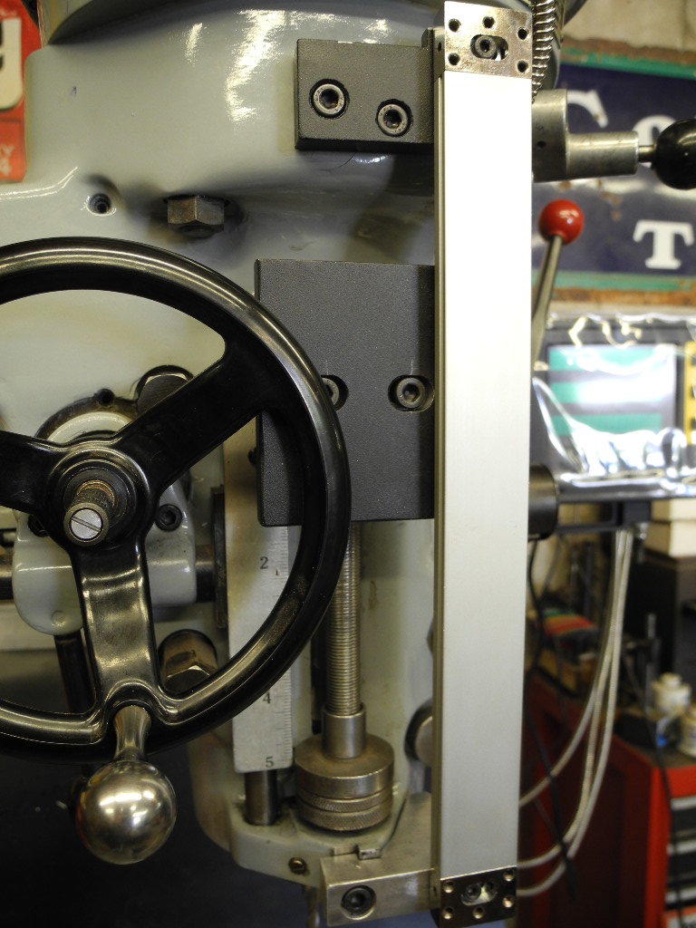
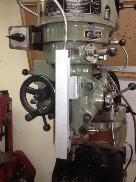
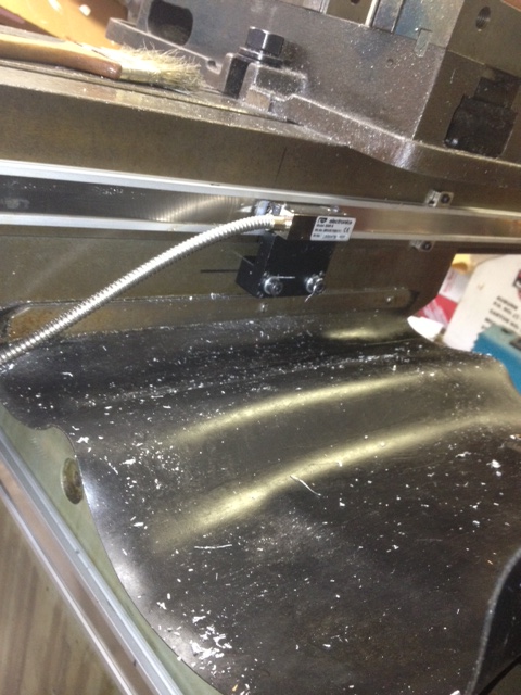
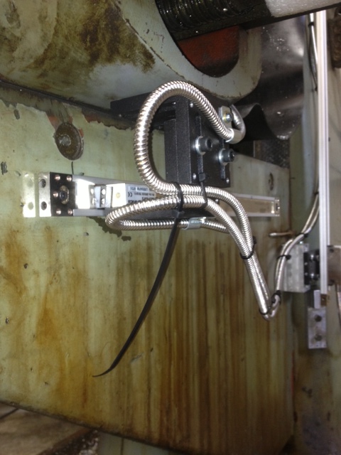
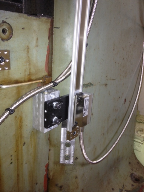
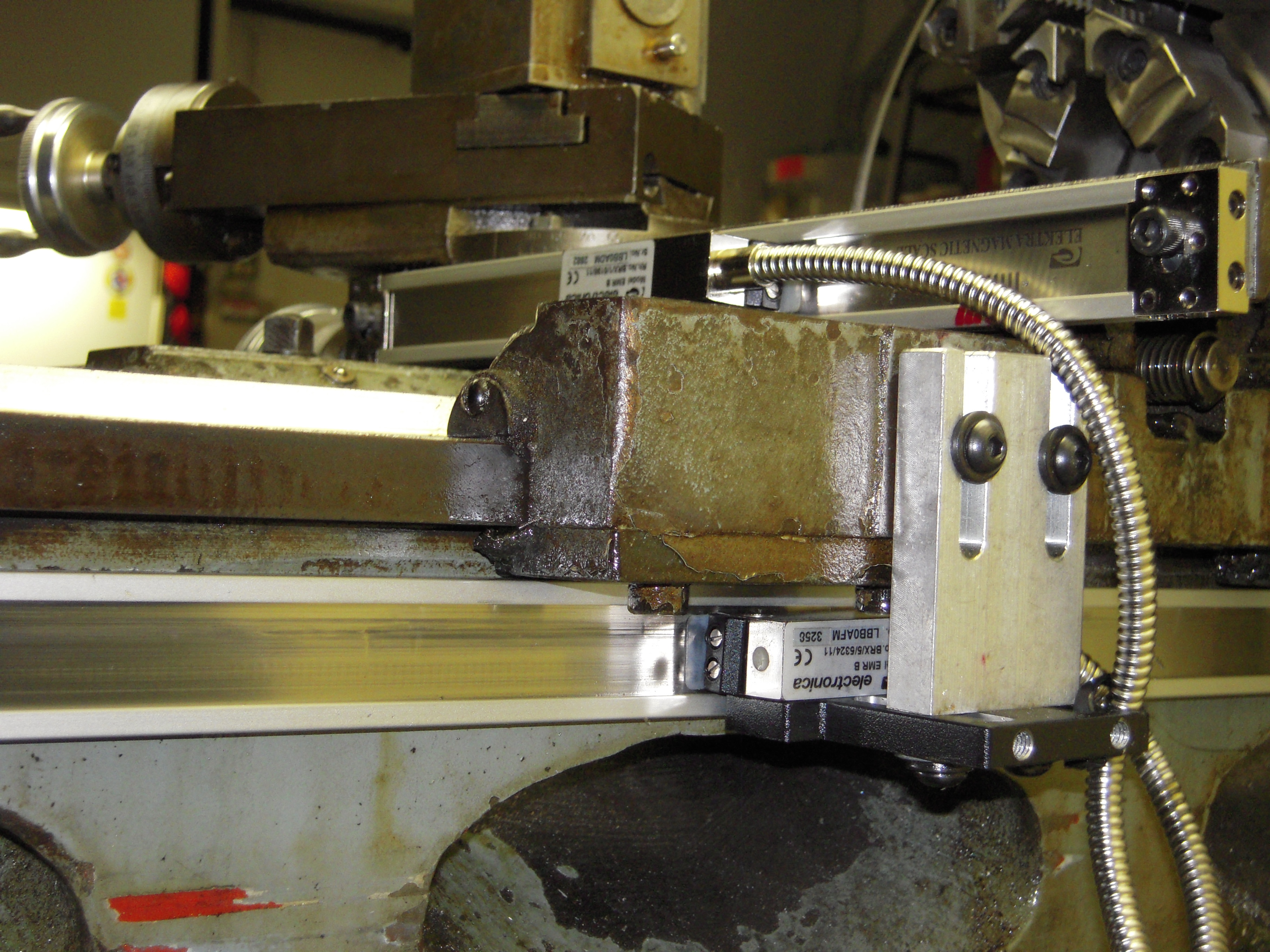
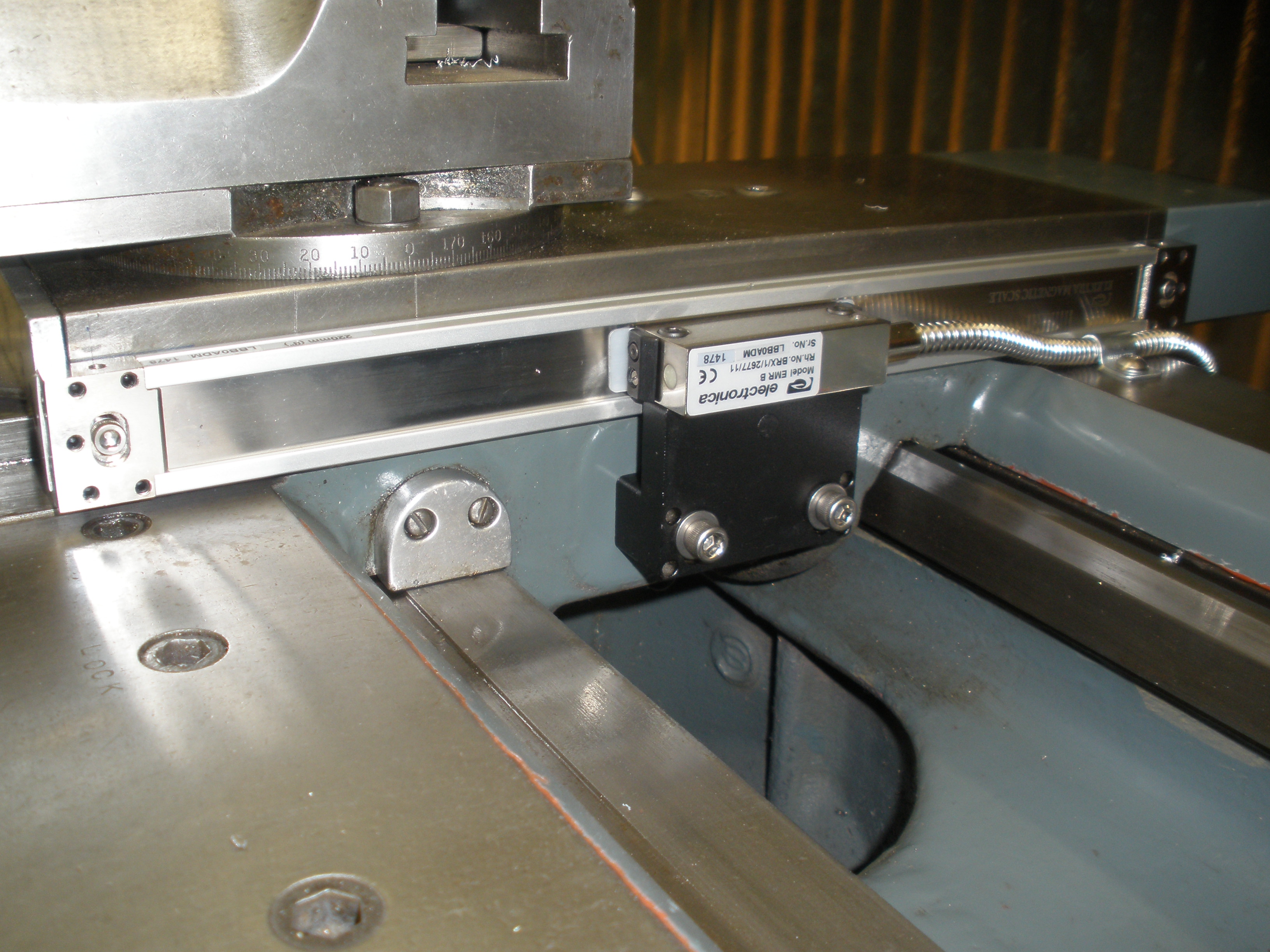
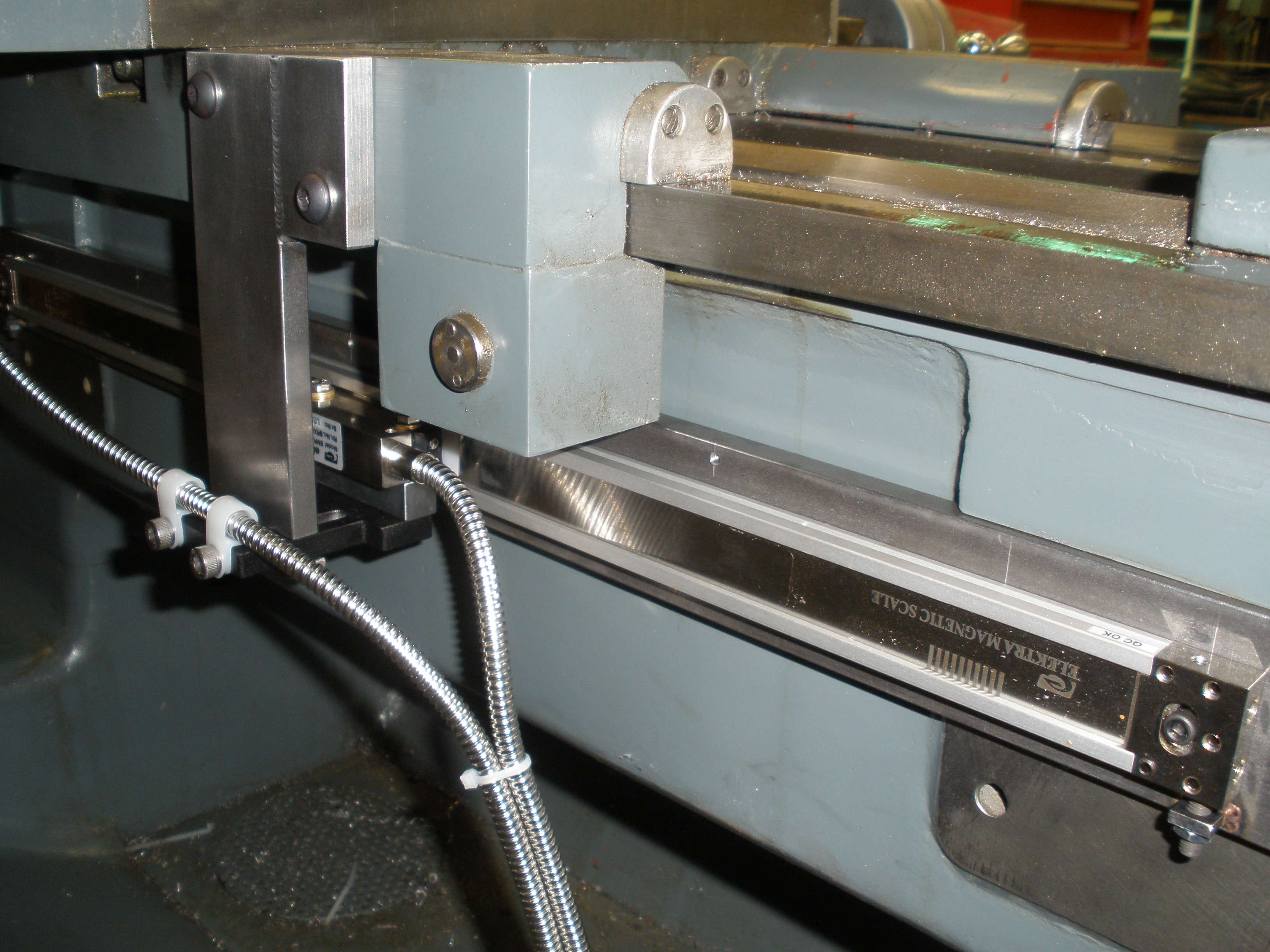
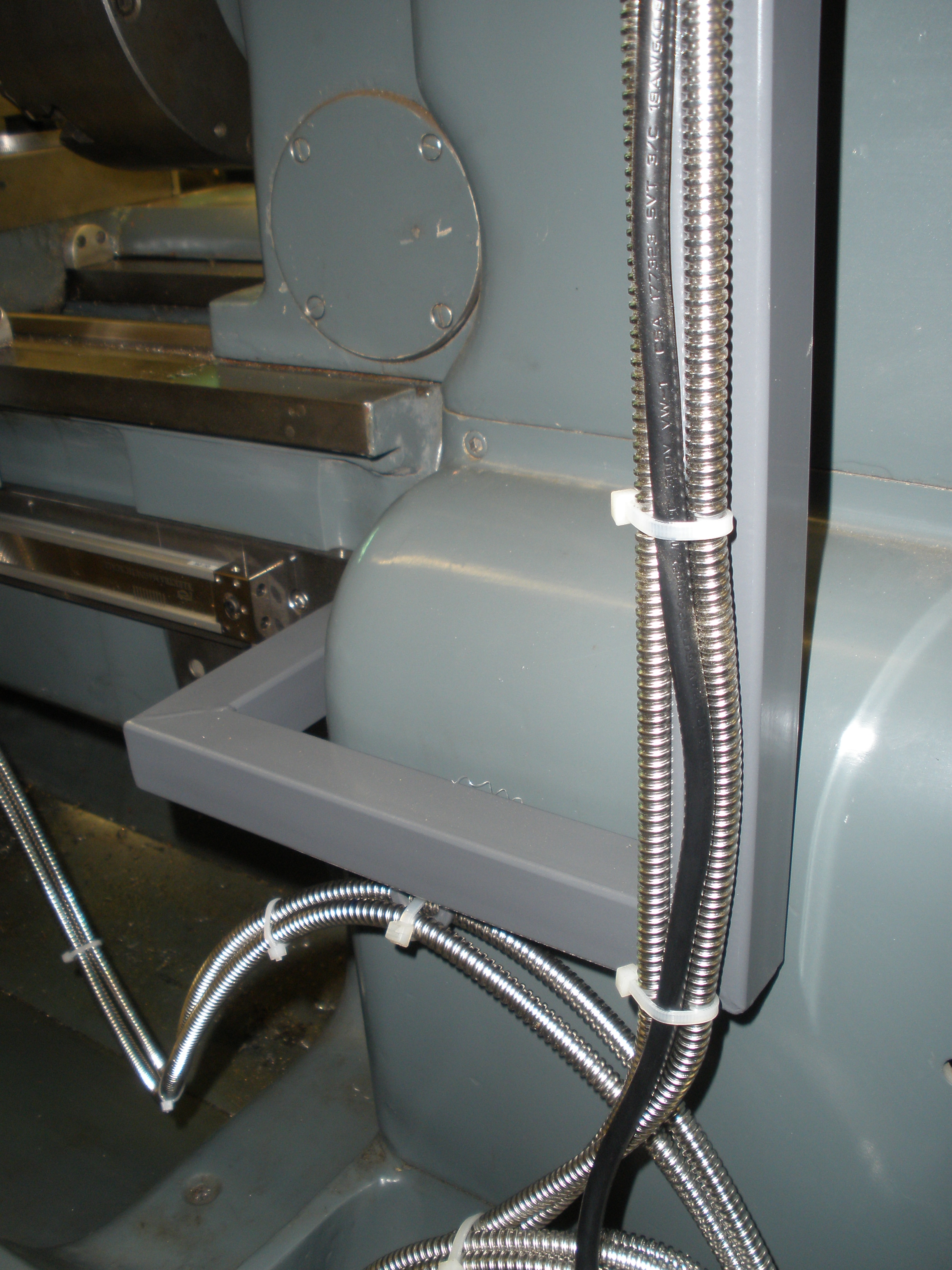
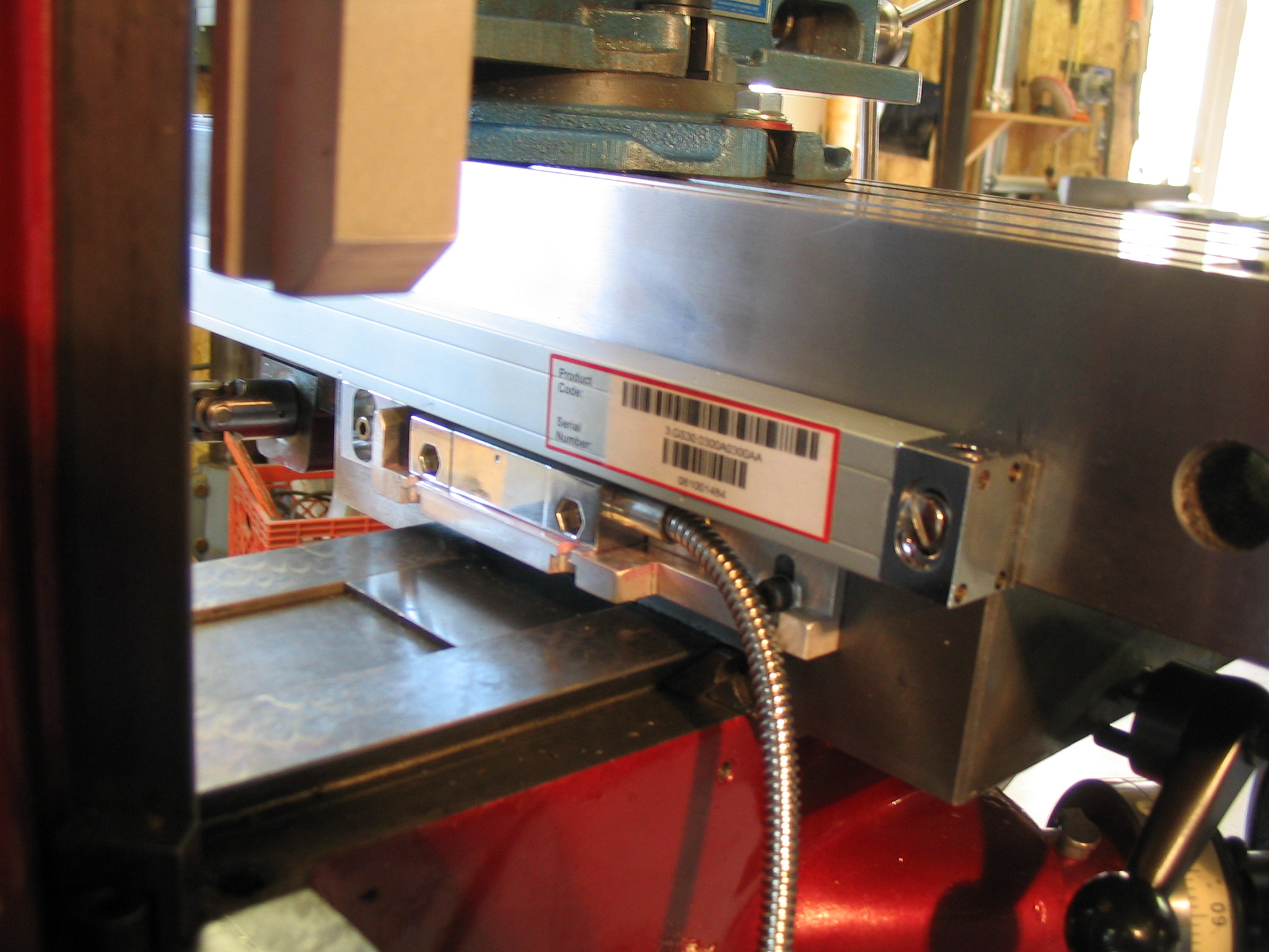
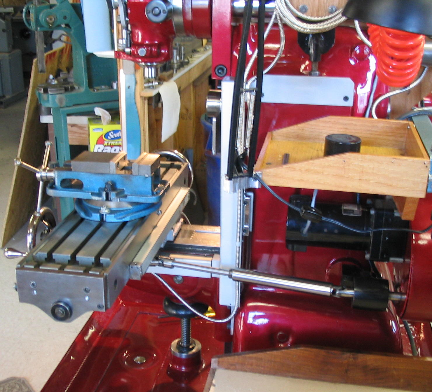
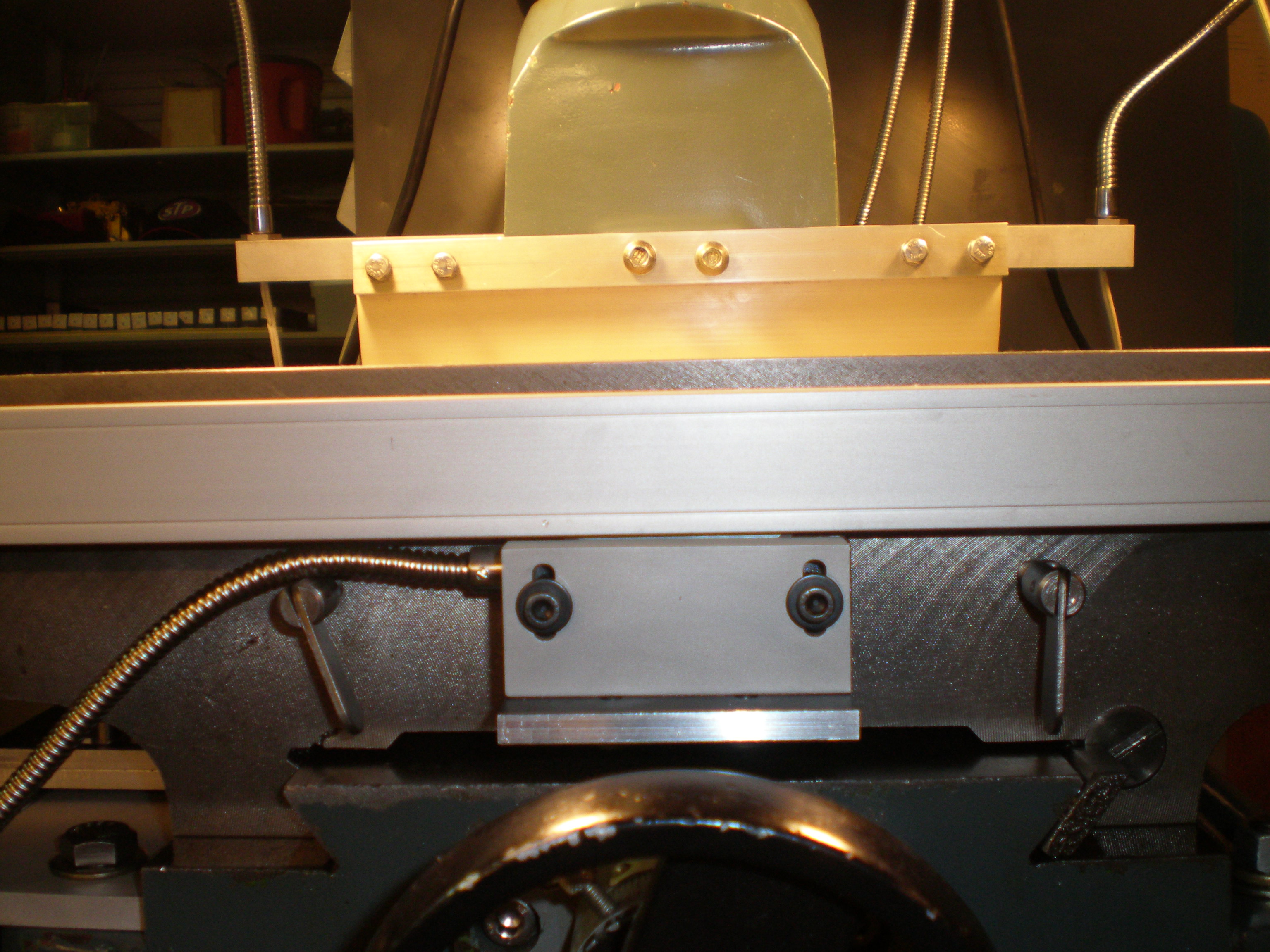
#2 - Courtesy
of P. Smith with the new MagnaSlim Magnetic Scale
Lathe Kit:

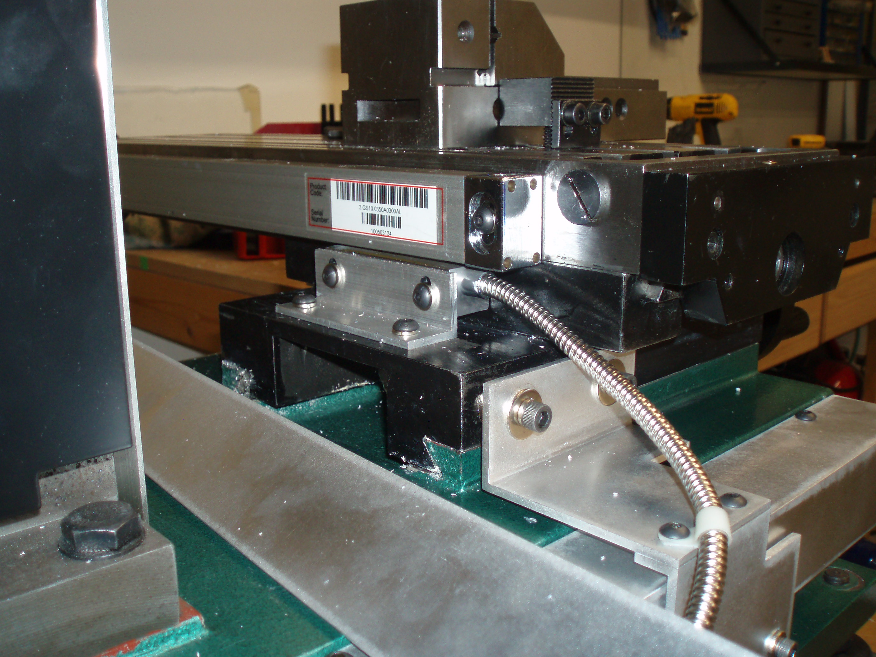
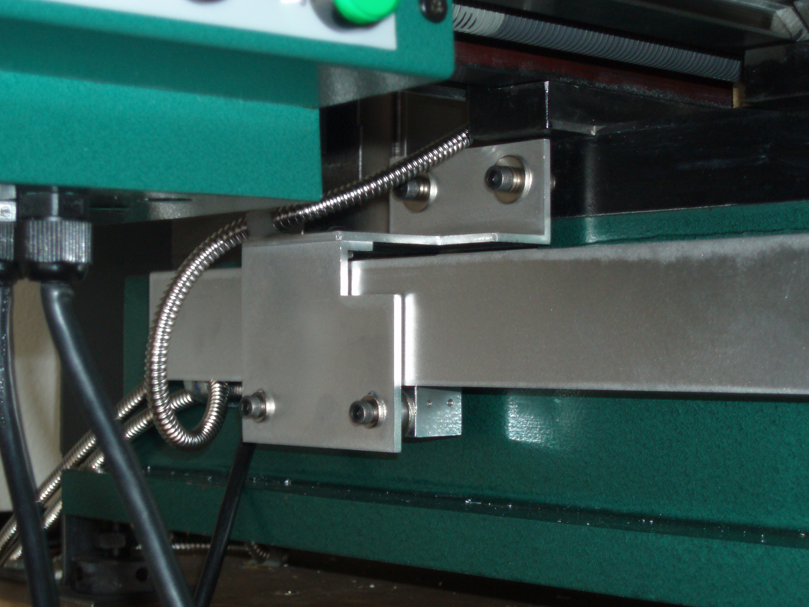
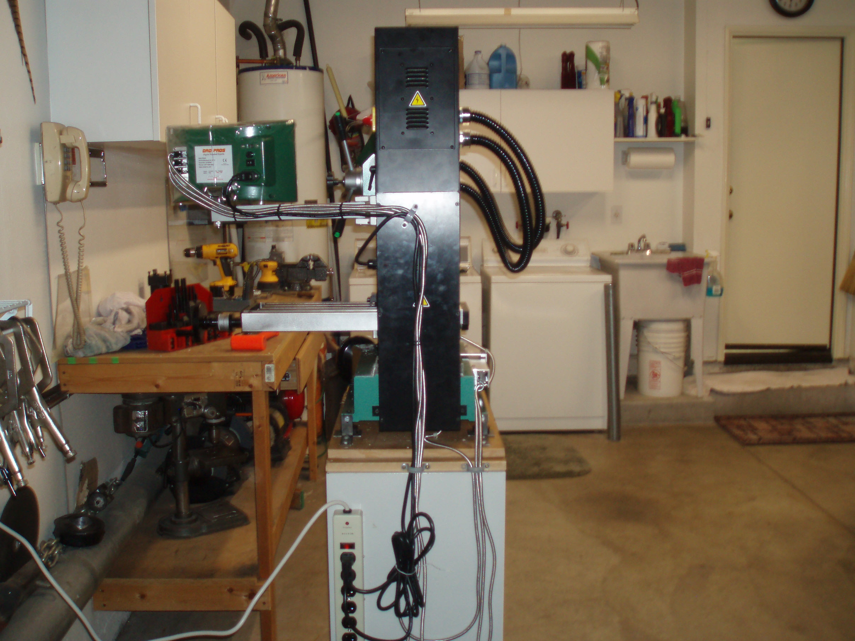
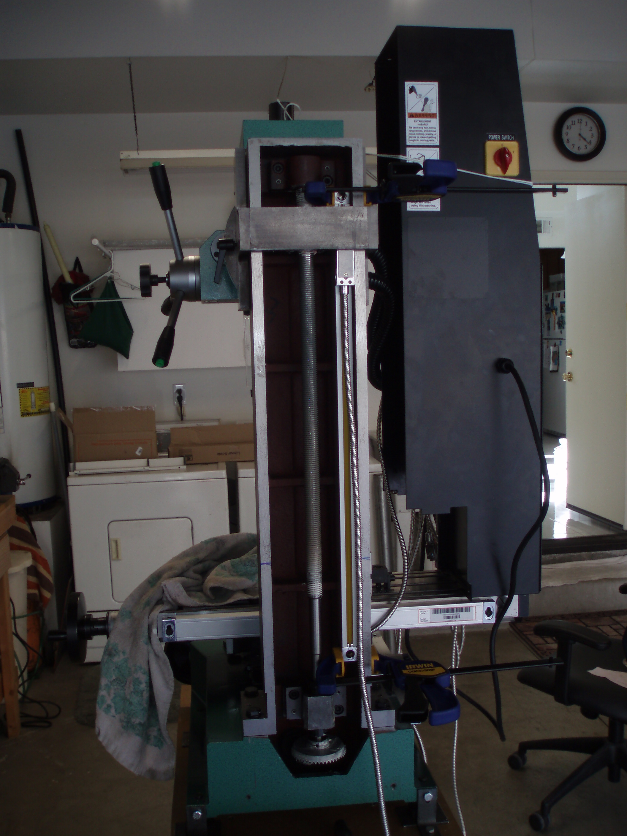
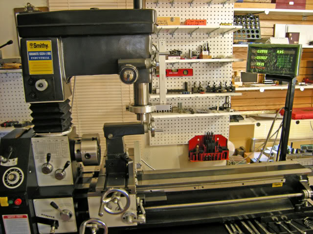
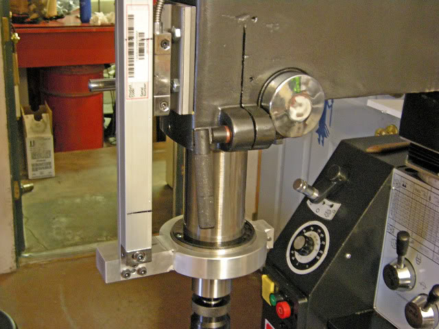
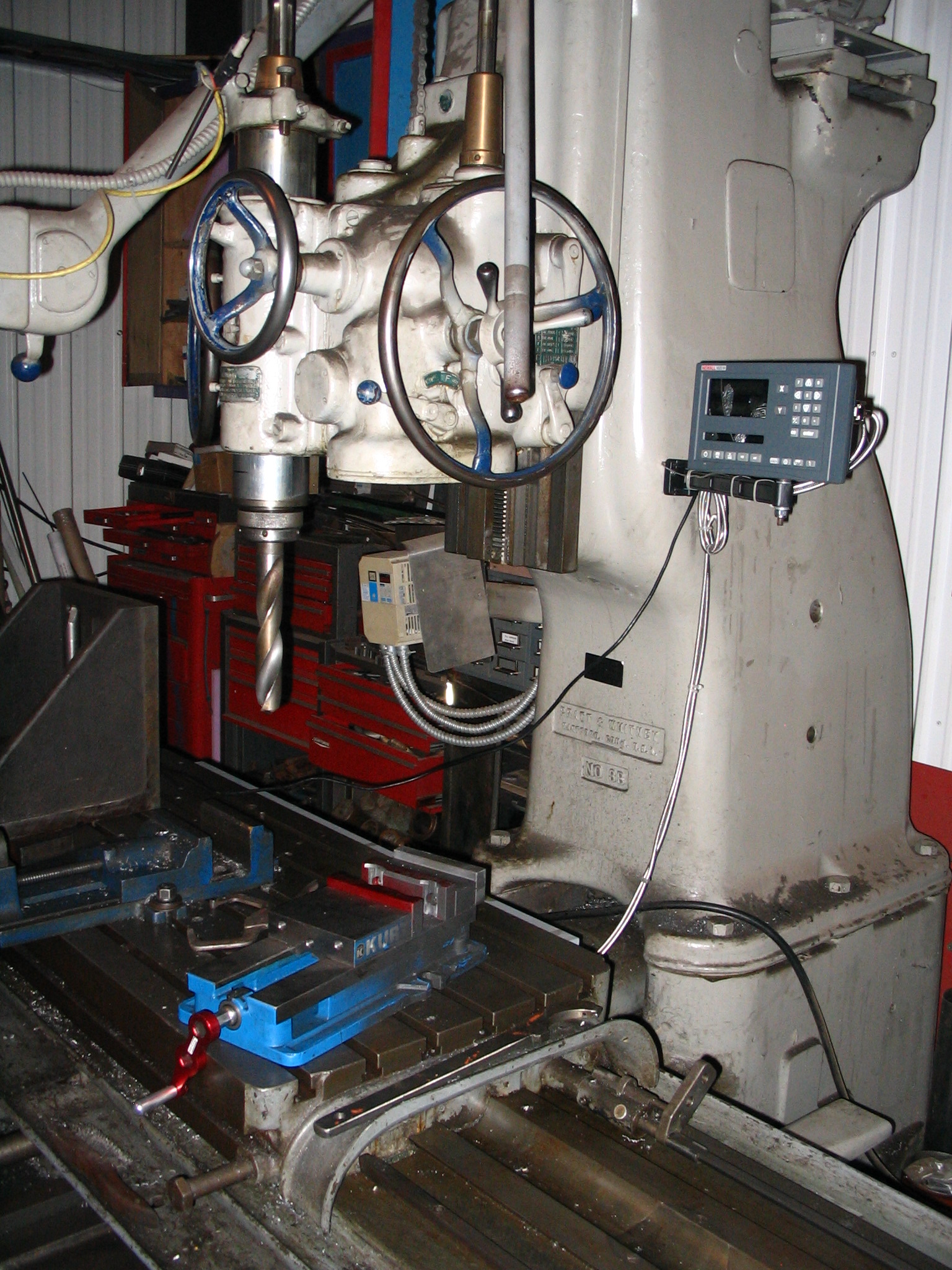
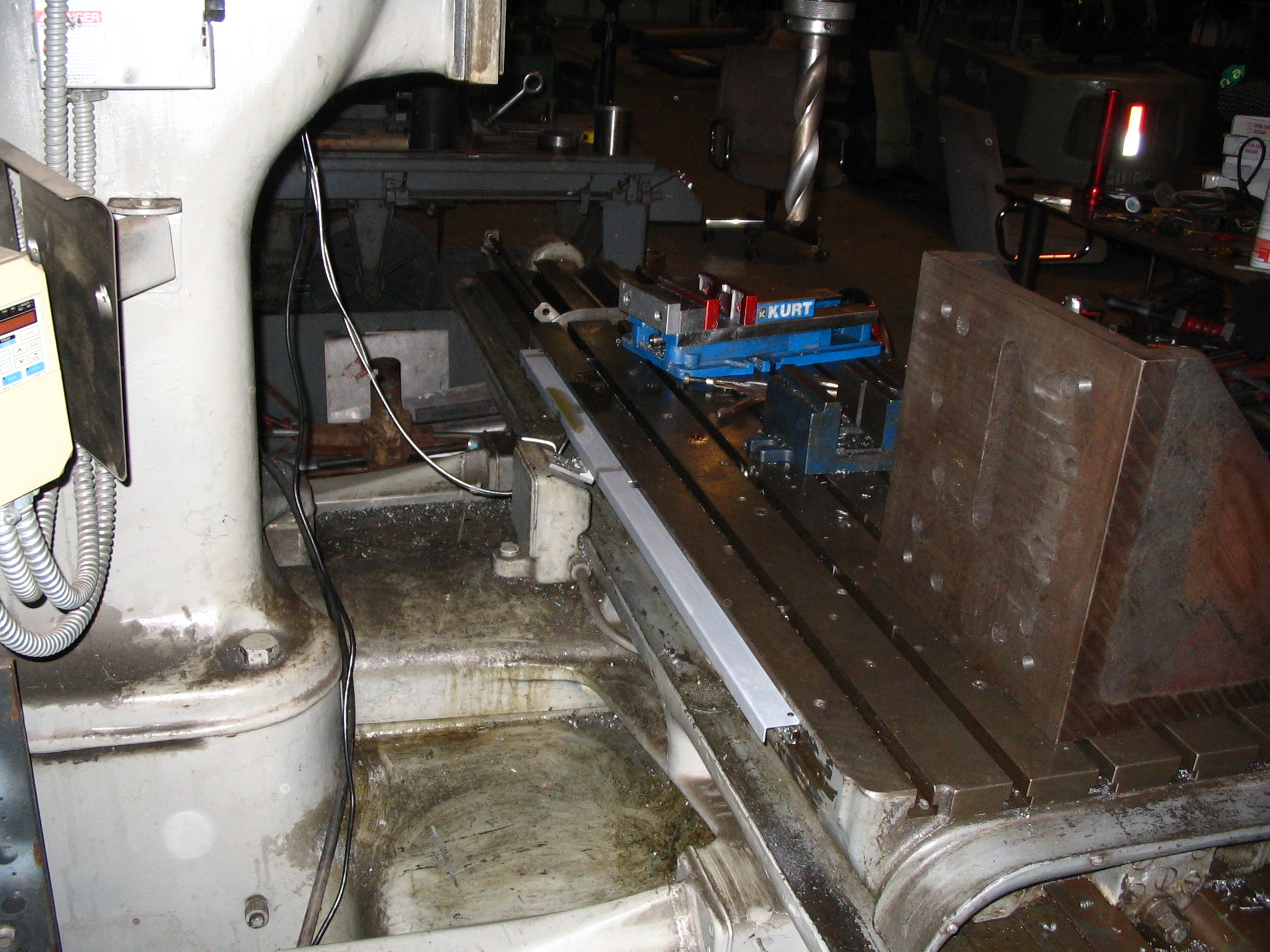
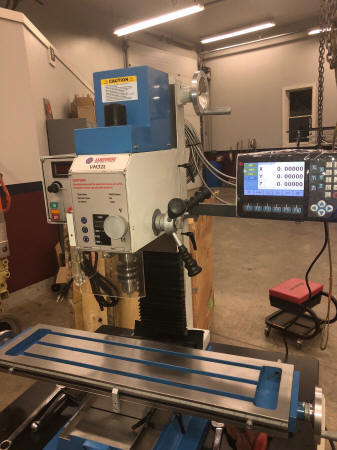
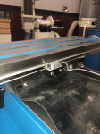
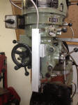
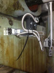
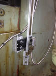
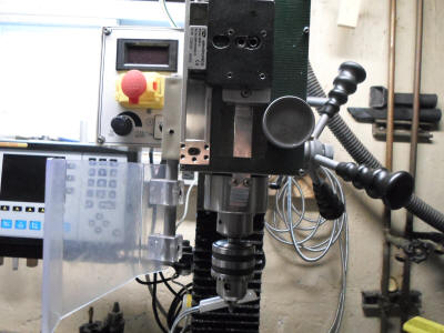
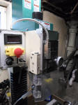
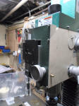
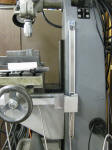
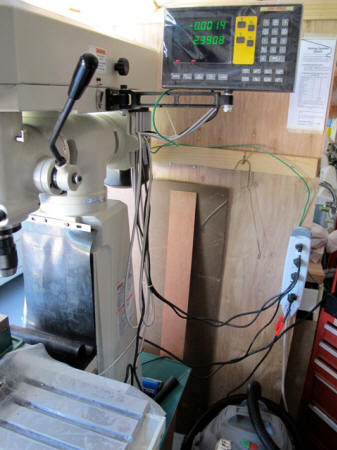
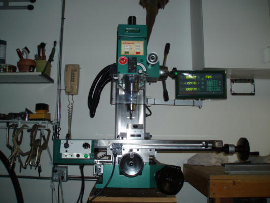
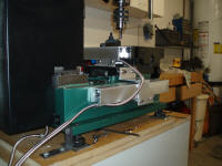
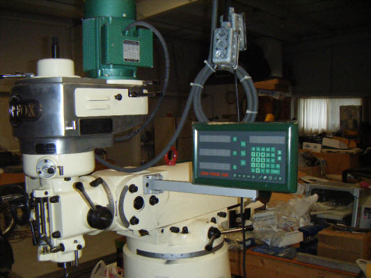
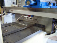
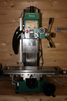
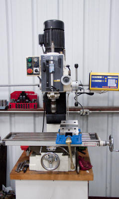
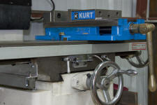
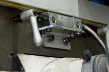
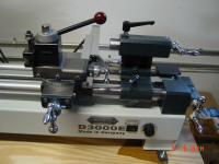
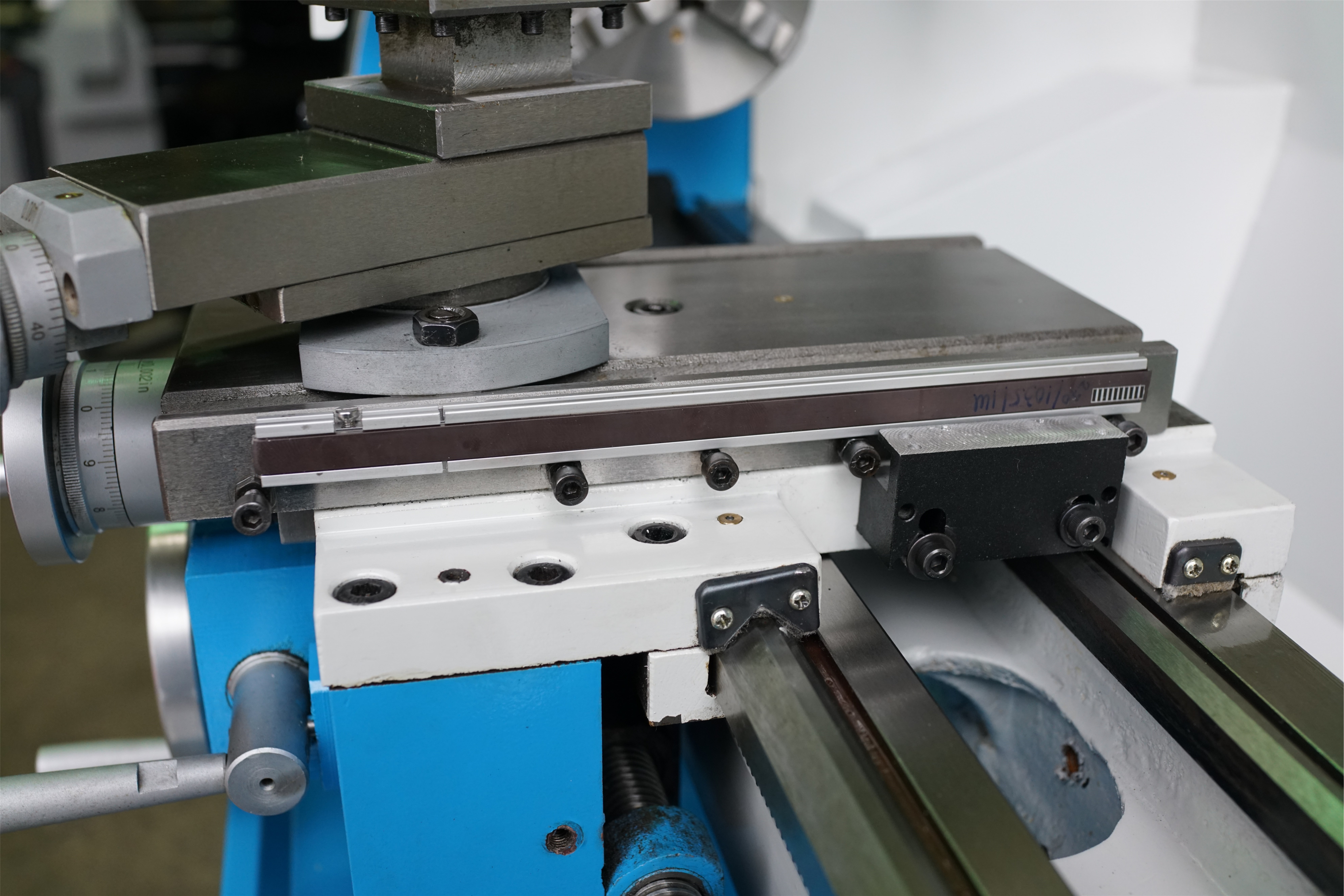
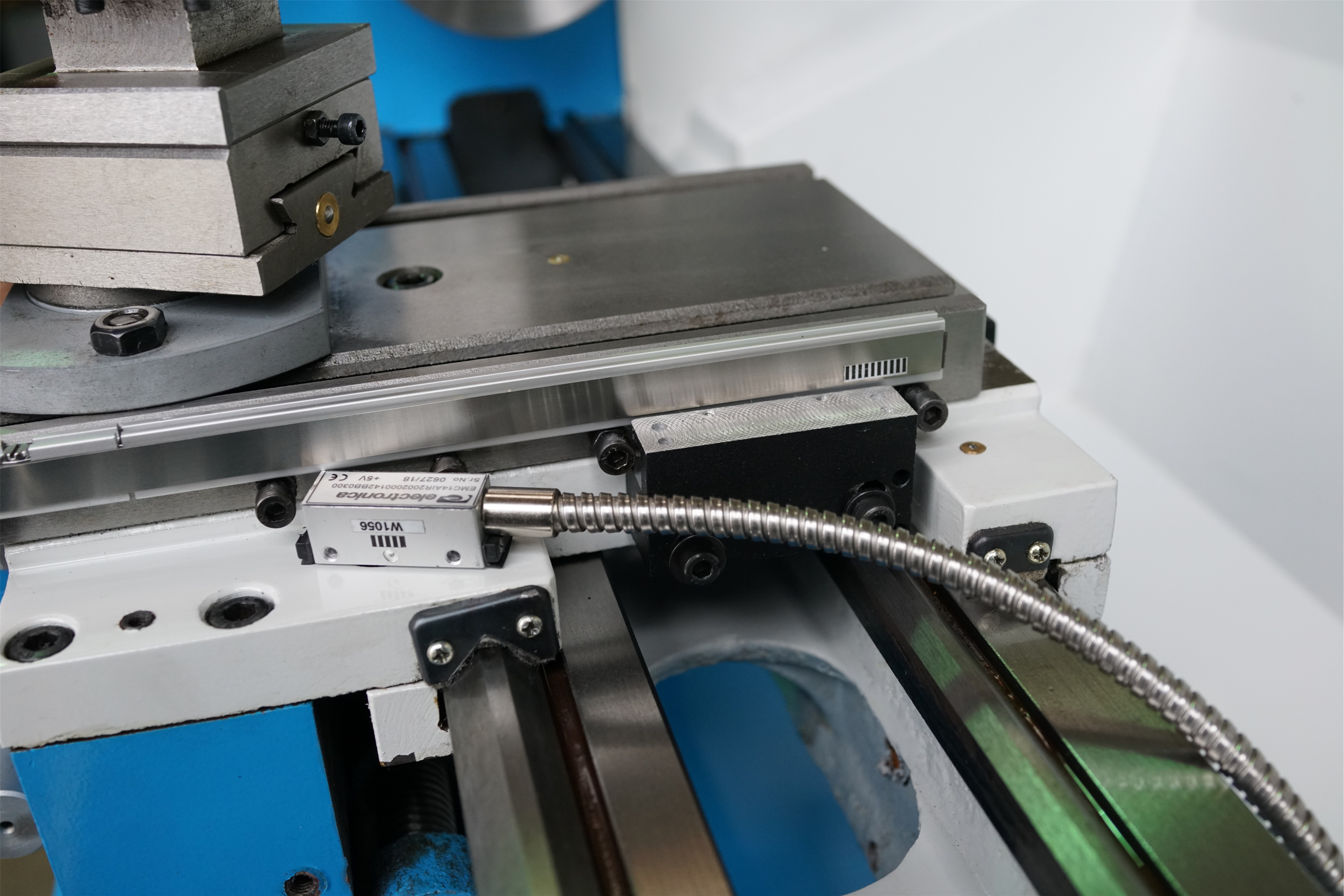
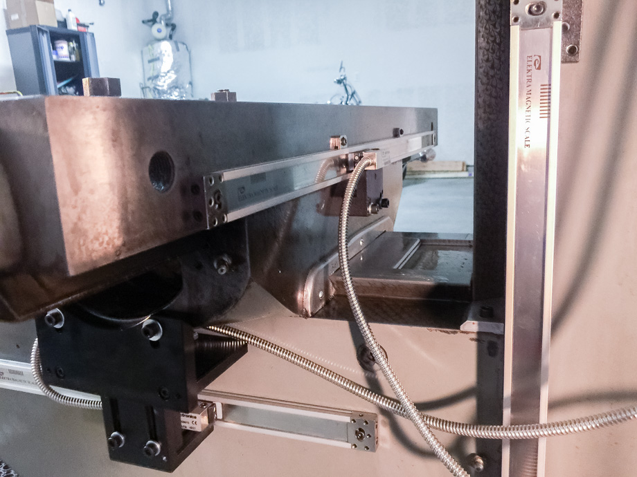
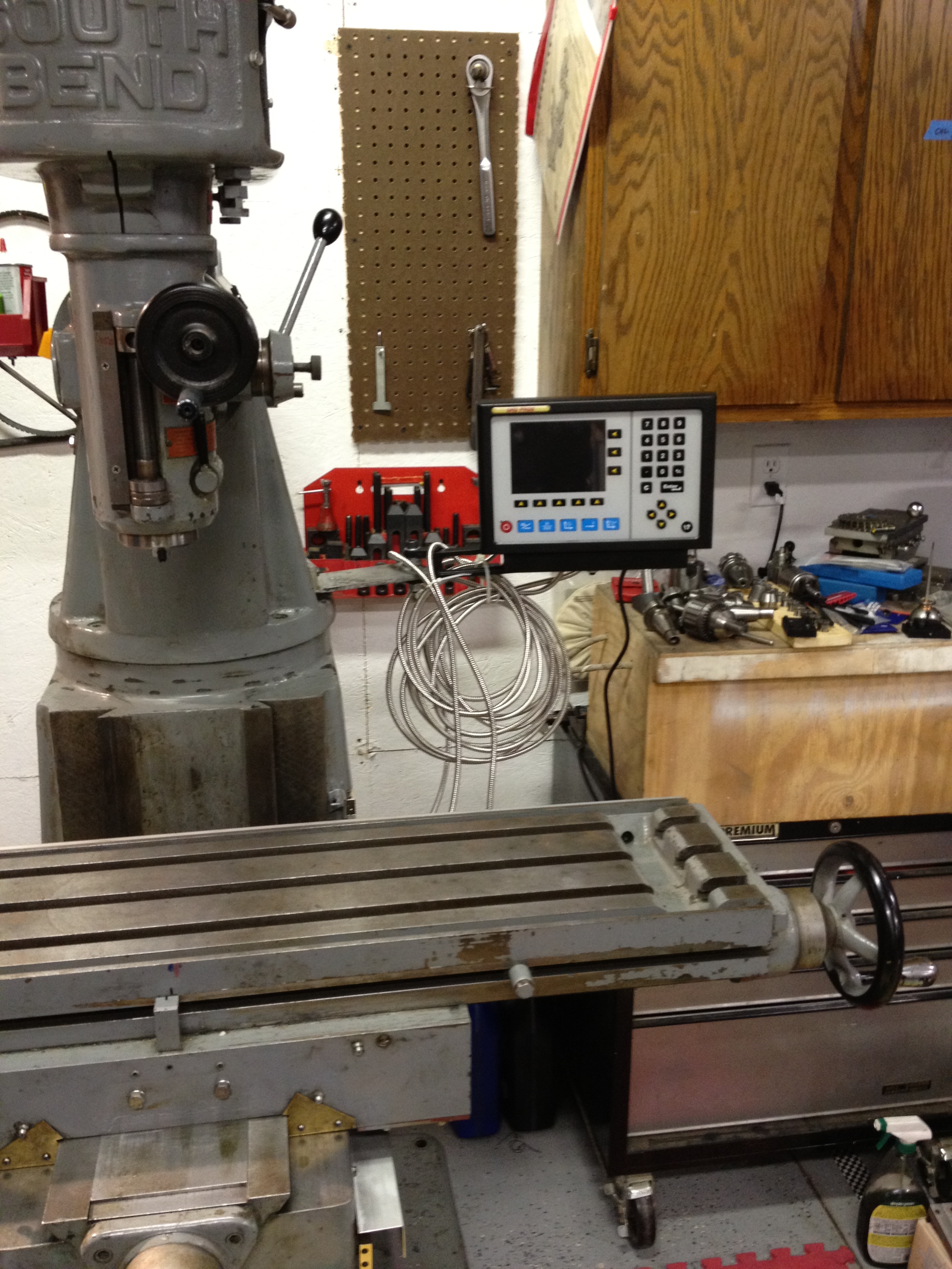
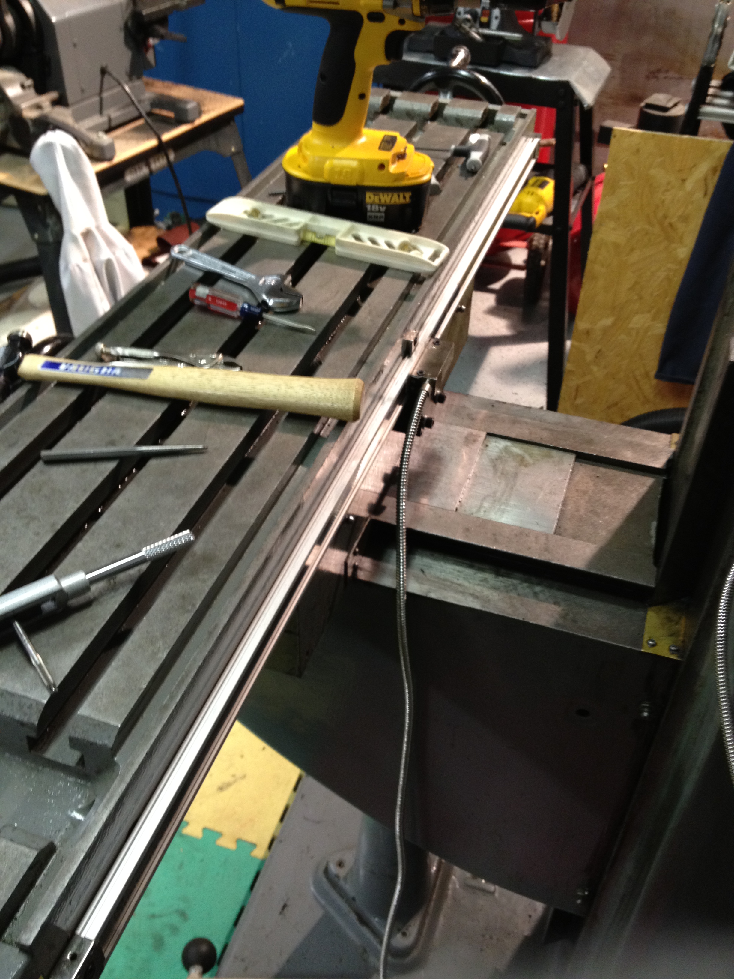
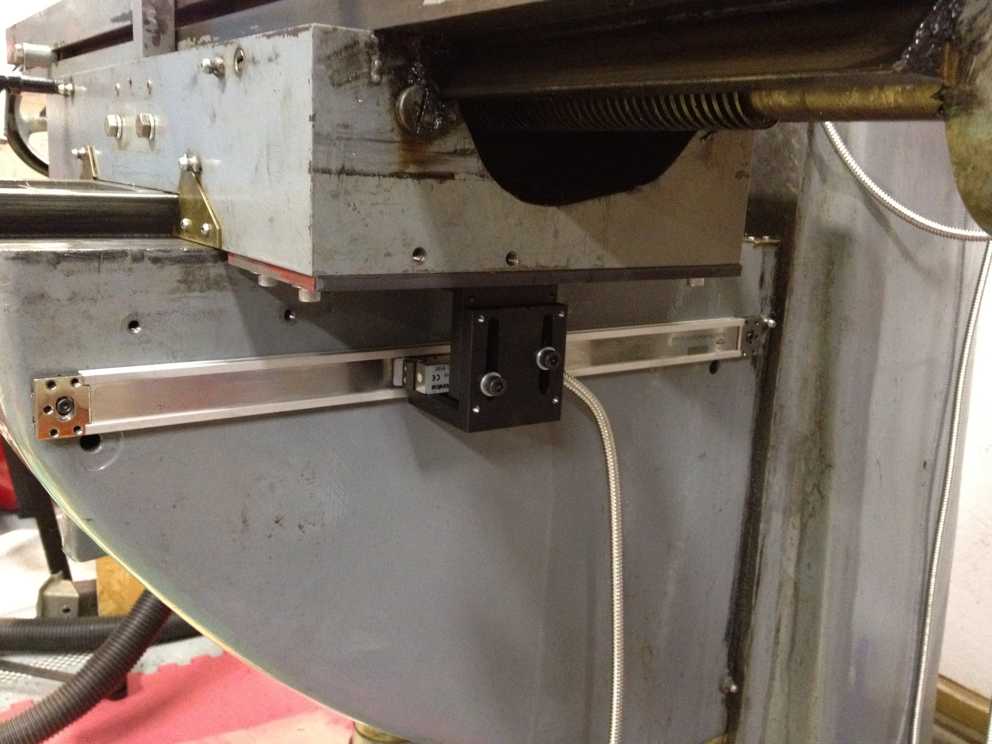
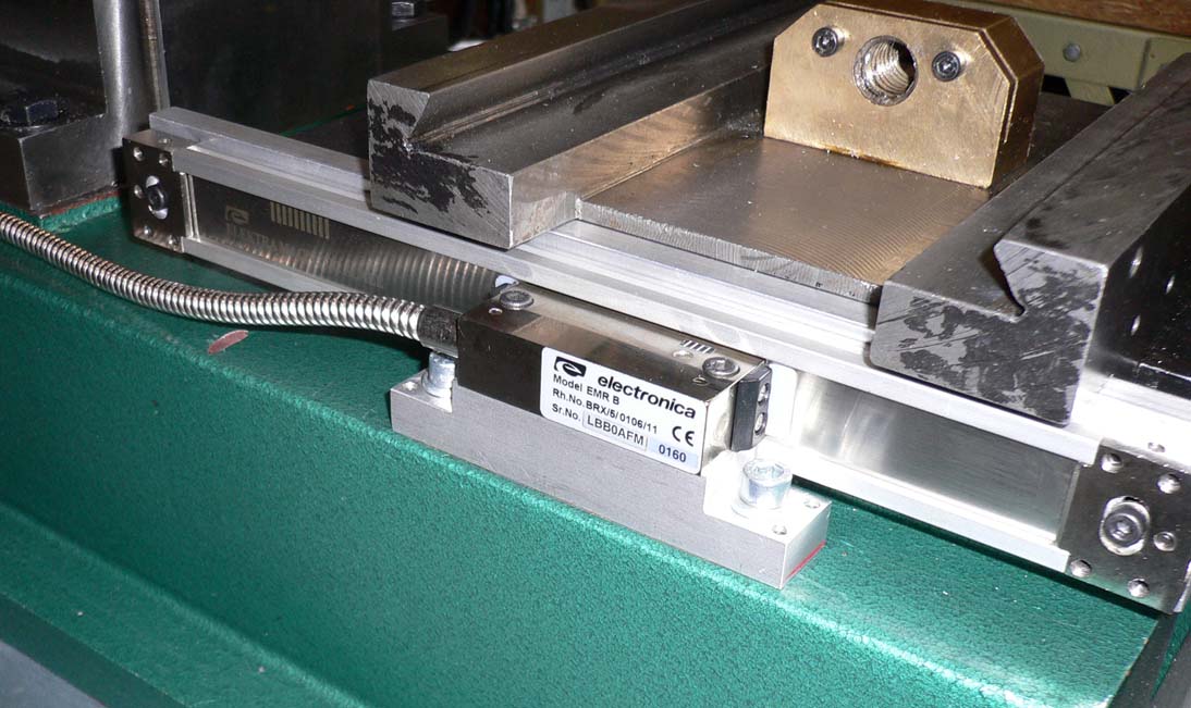
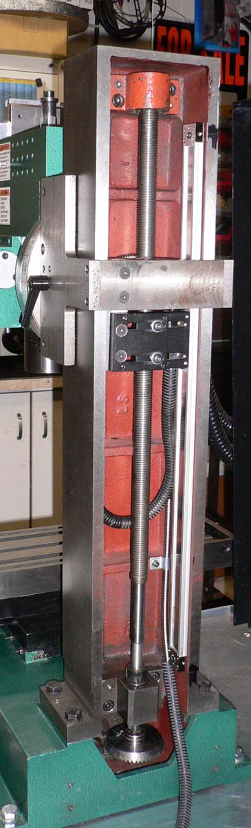
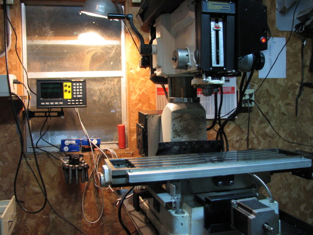
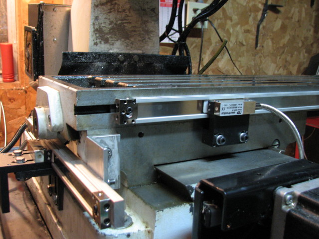
#3 - Courtesy
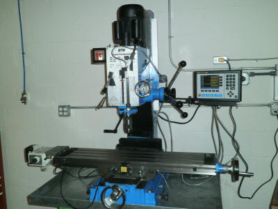
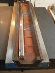
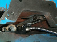
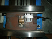
of M. Steinbeck with the new MagnaSlim Magnetic Scales on his Weiss
Mill:
  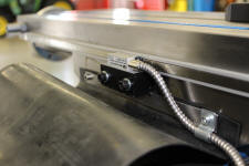  
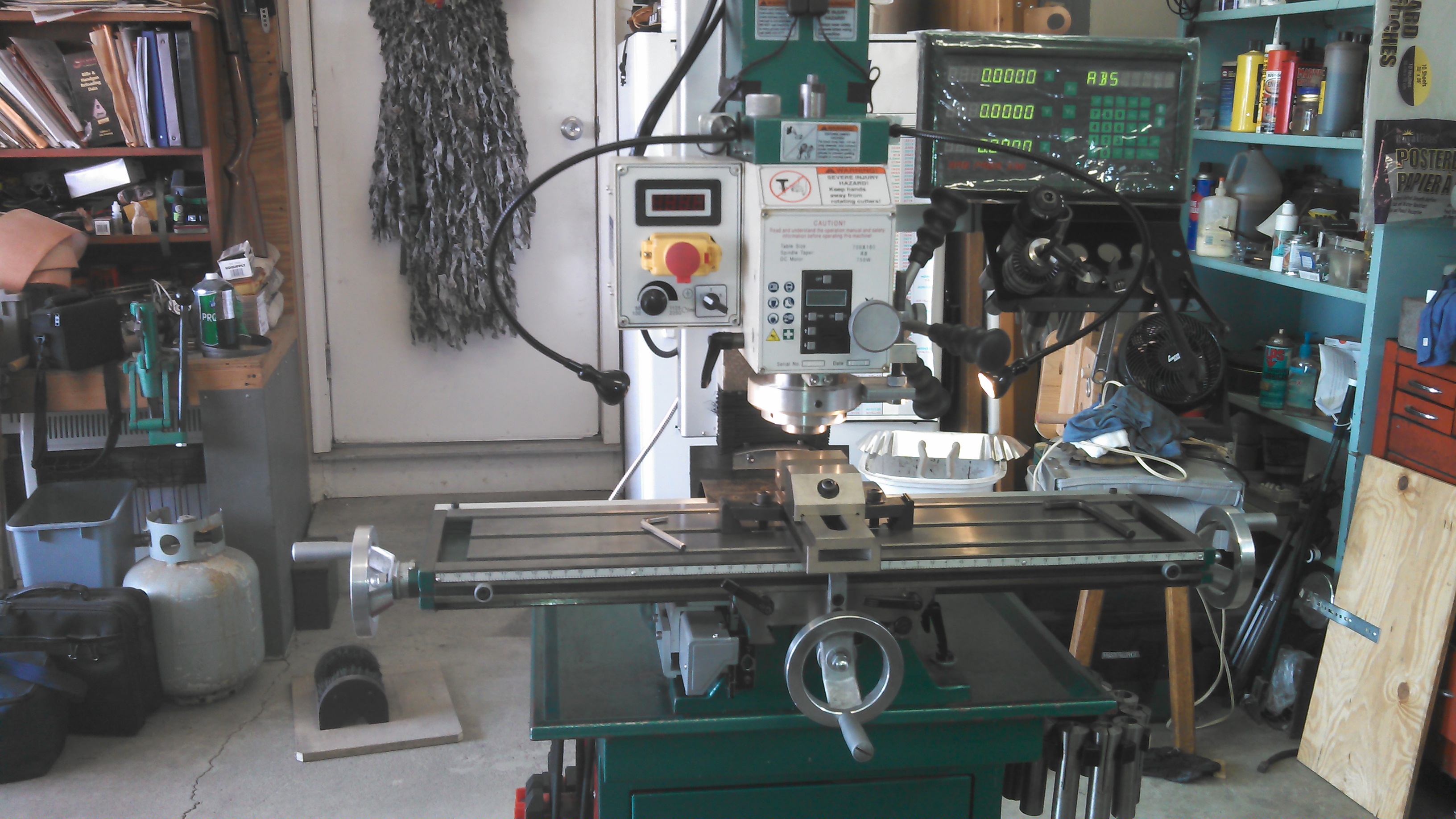
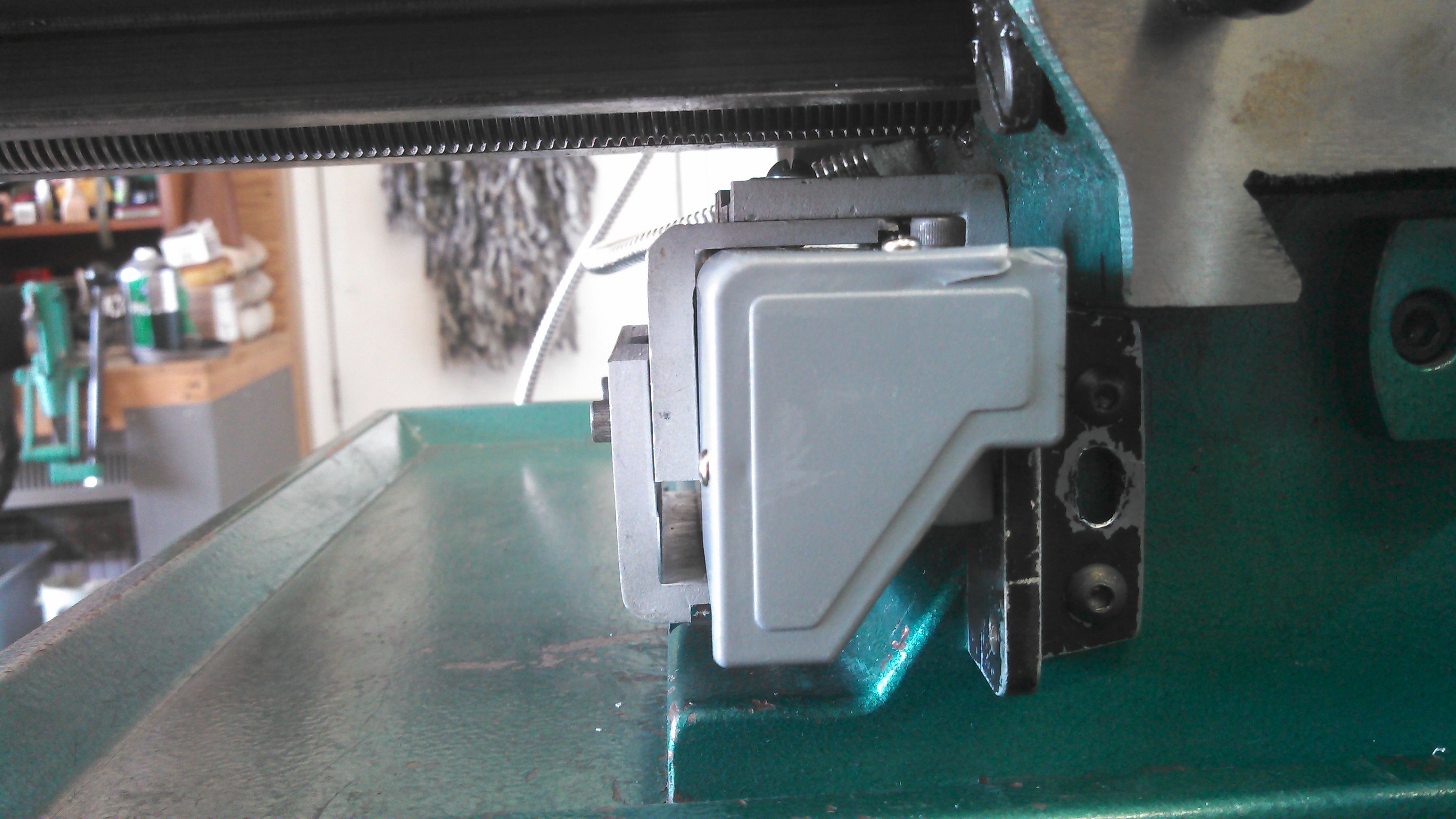
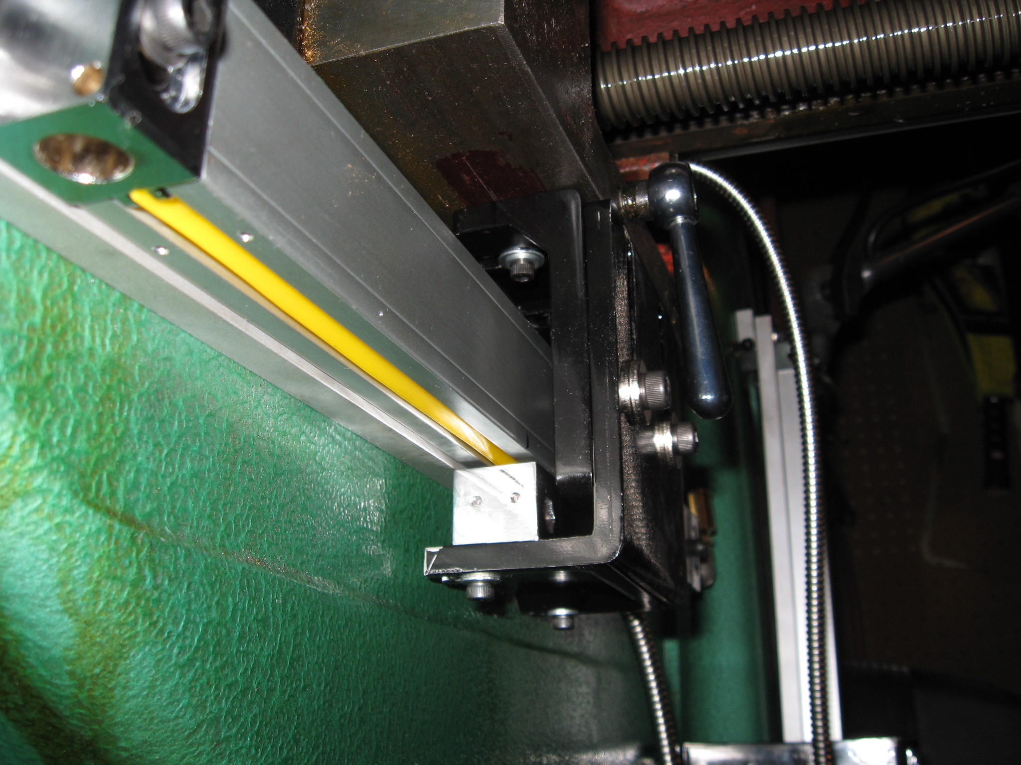
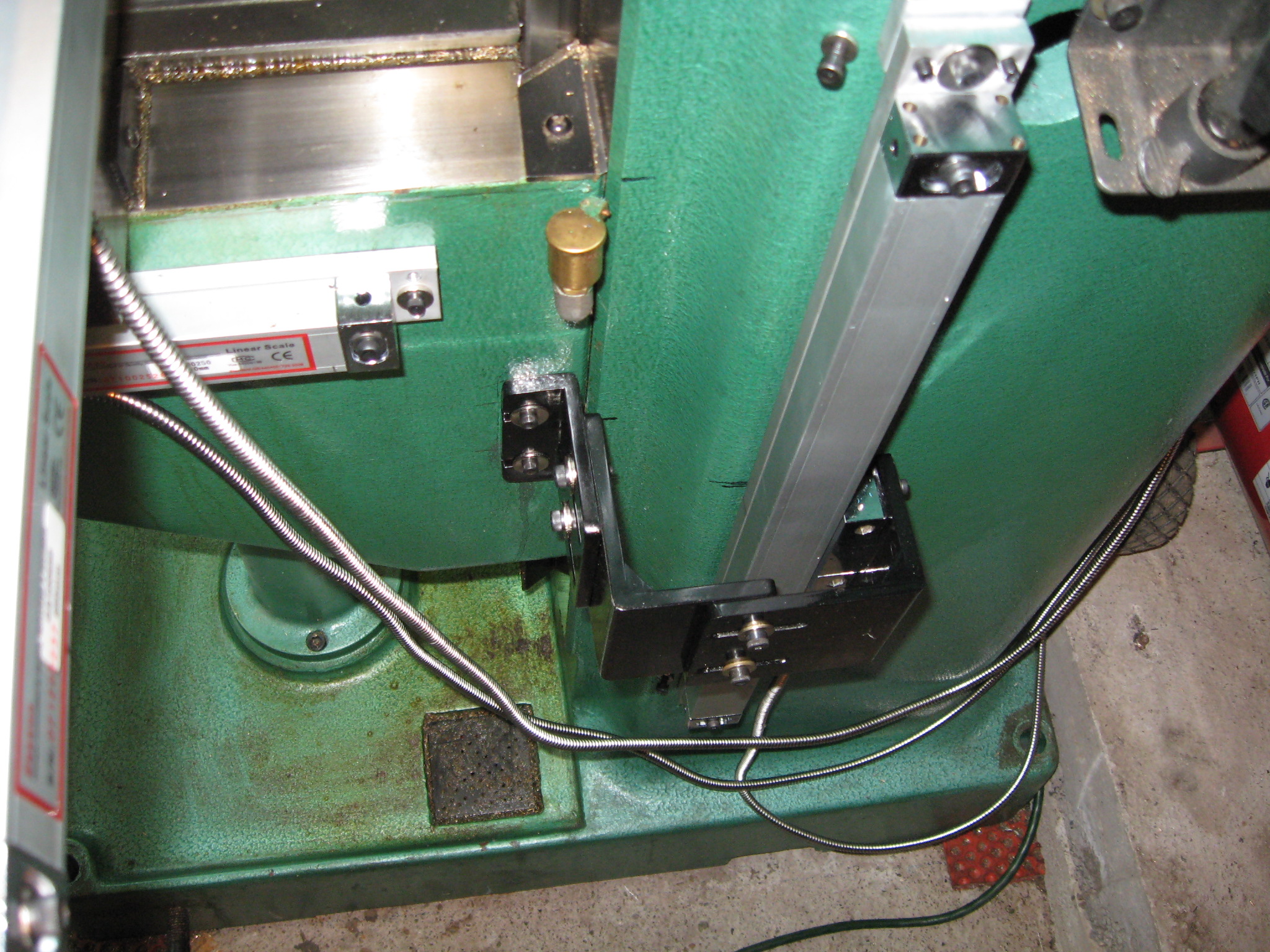
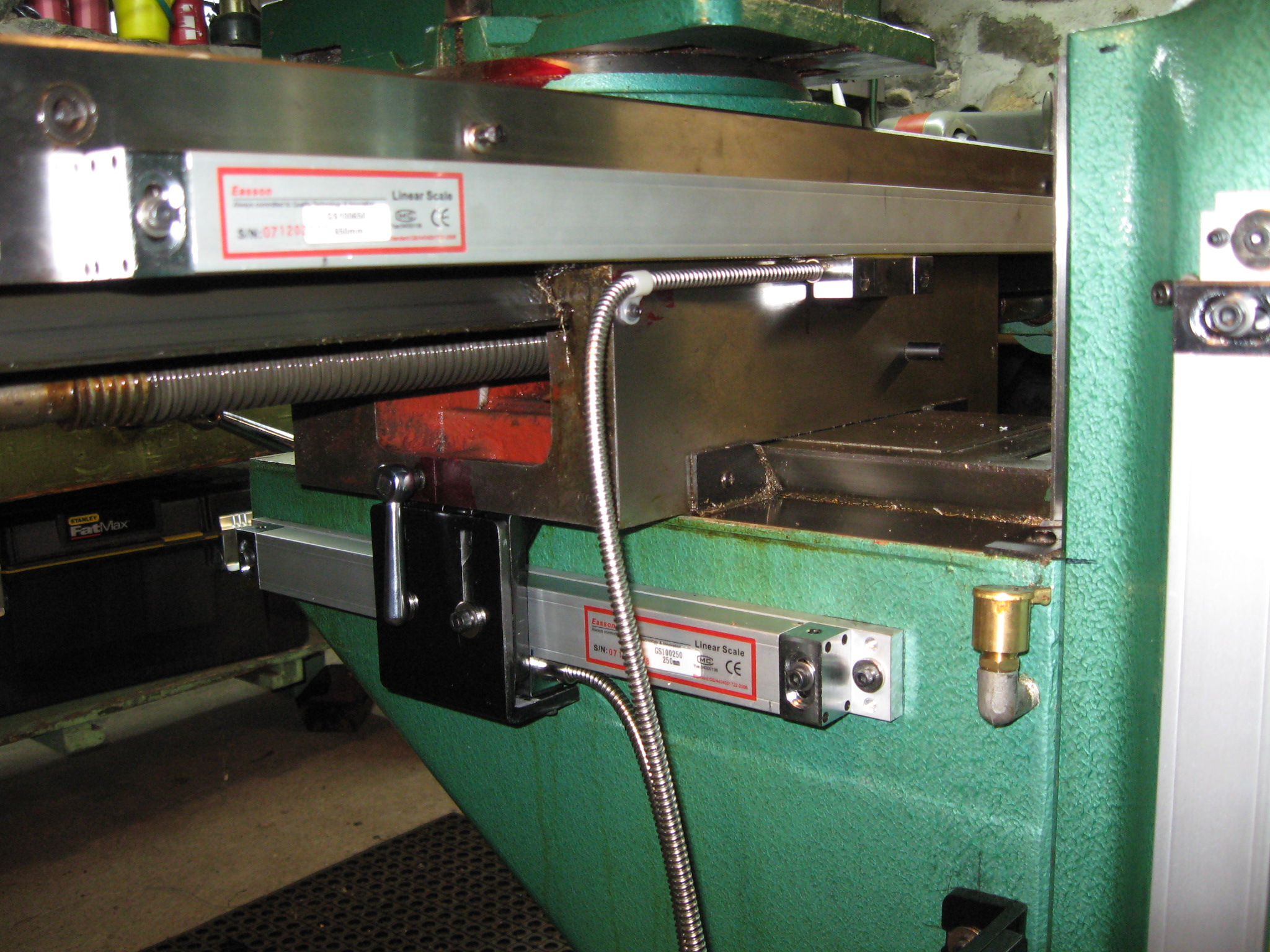
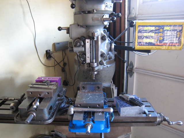
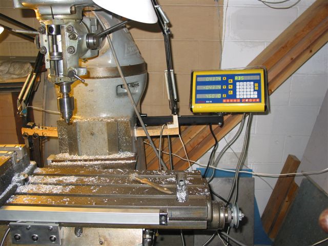
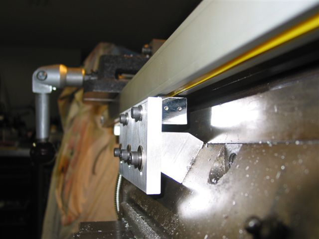
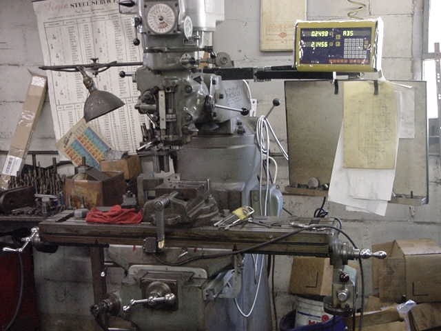
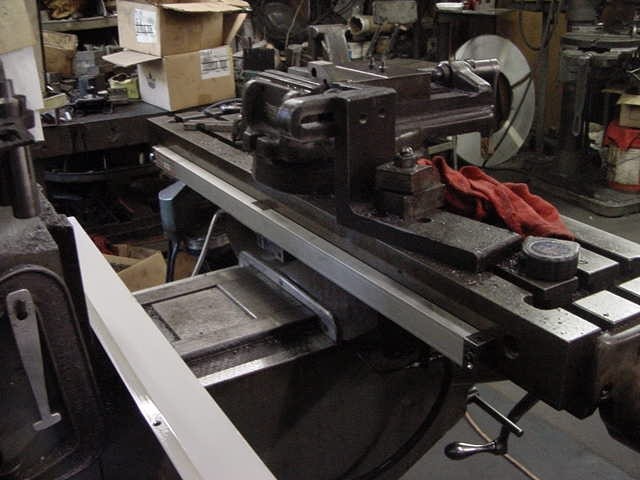
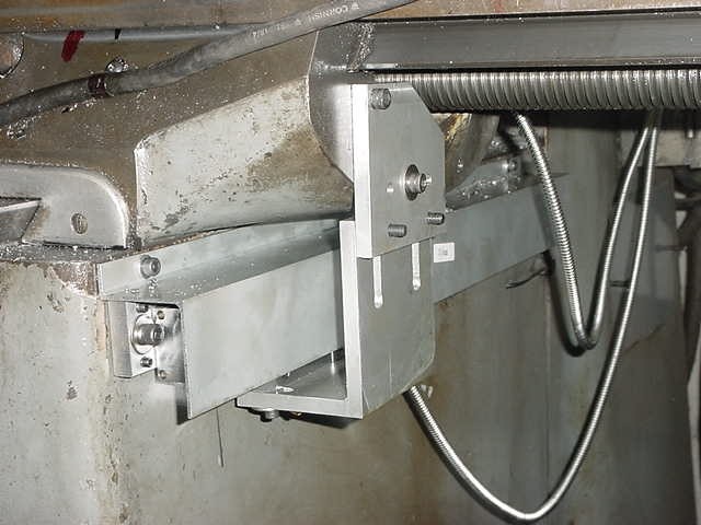
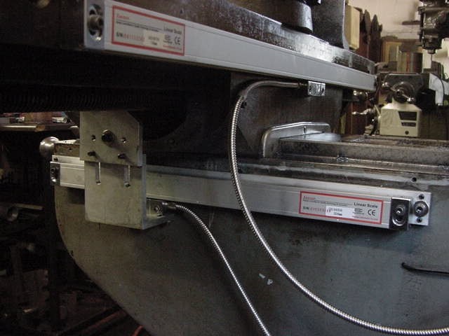
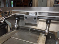
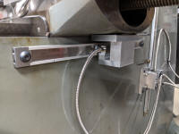
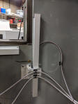
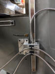
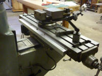
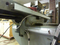
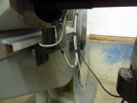
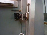
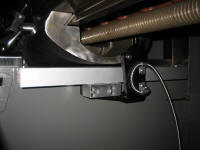
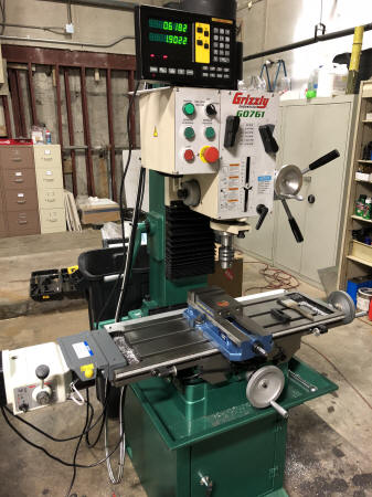
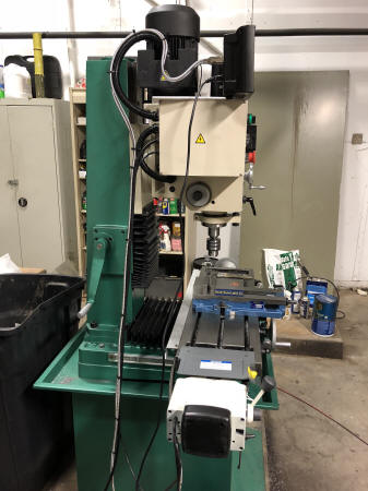
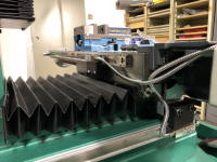
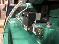
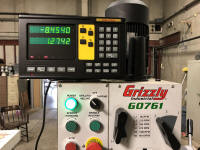
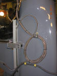
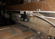
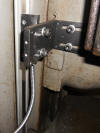
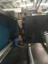
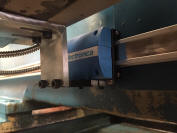
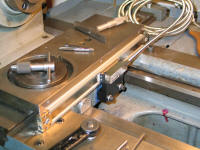
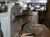
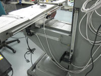
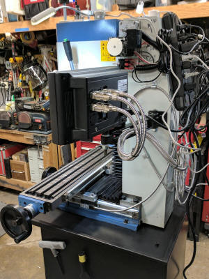
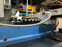
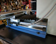
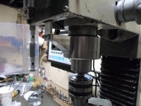
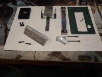
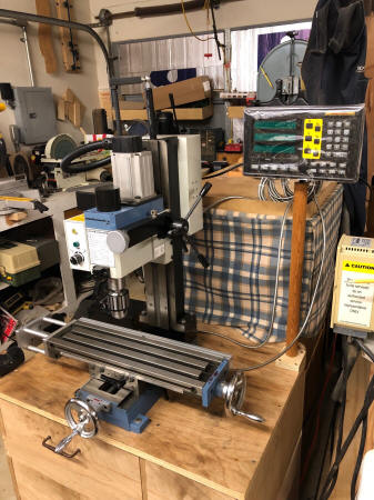
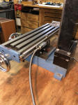
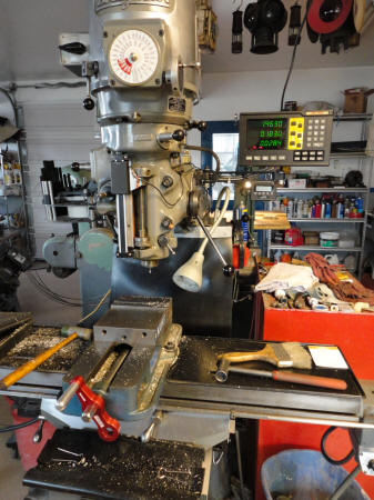
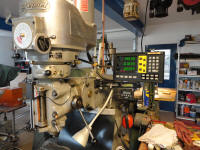
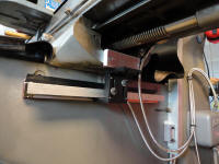
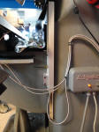
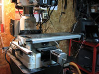
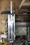
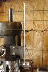
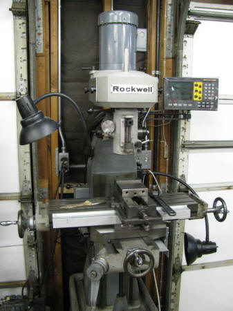
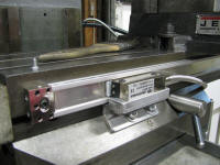
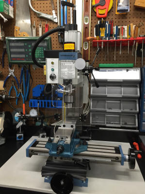
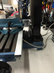
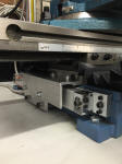
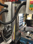
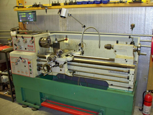
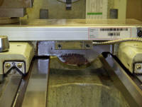
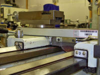
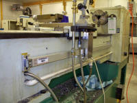
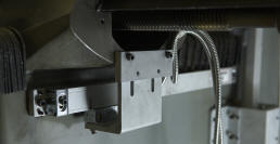
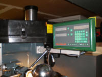
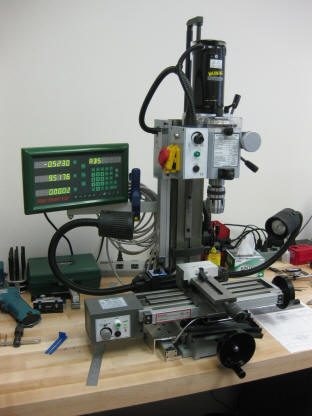
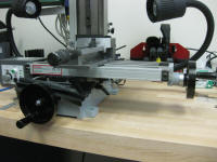
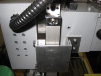
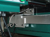
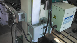
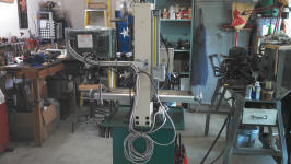
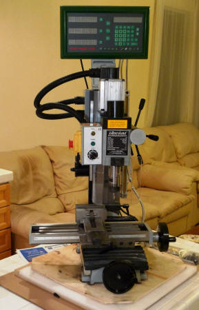
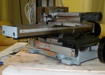
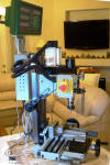
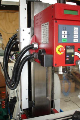
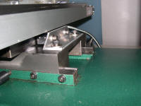
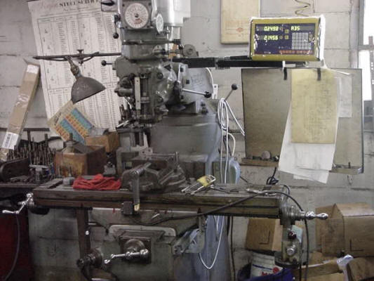
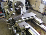
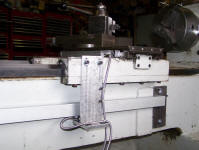
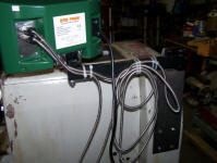
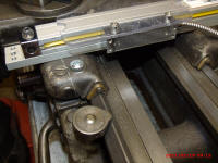
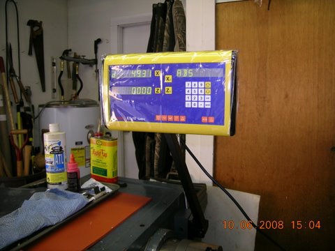
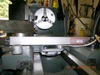
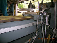
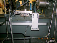
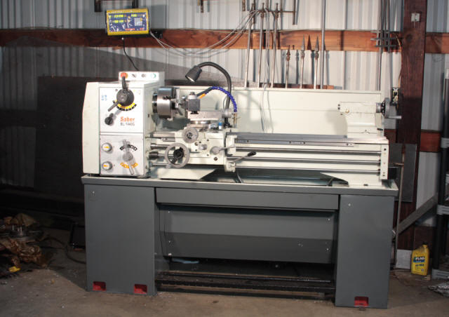
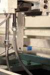
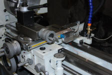
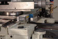
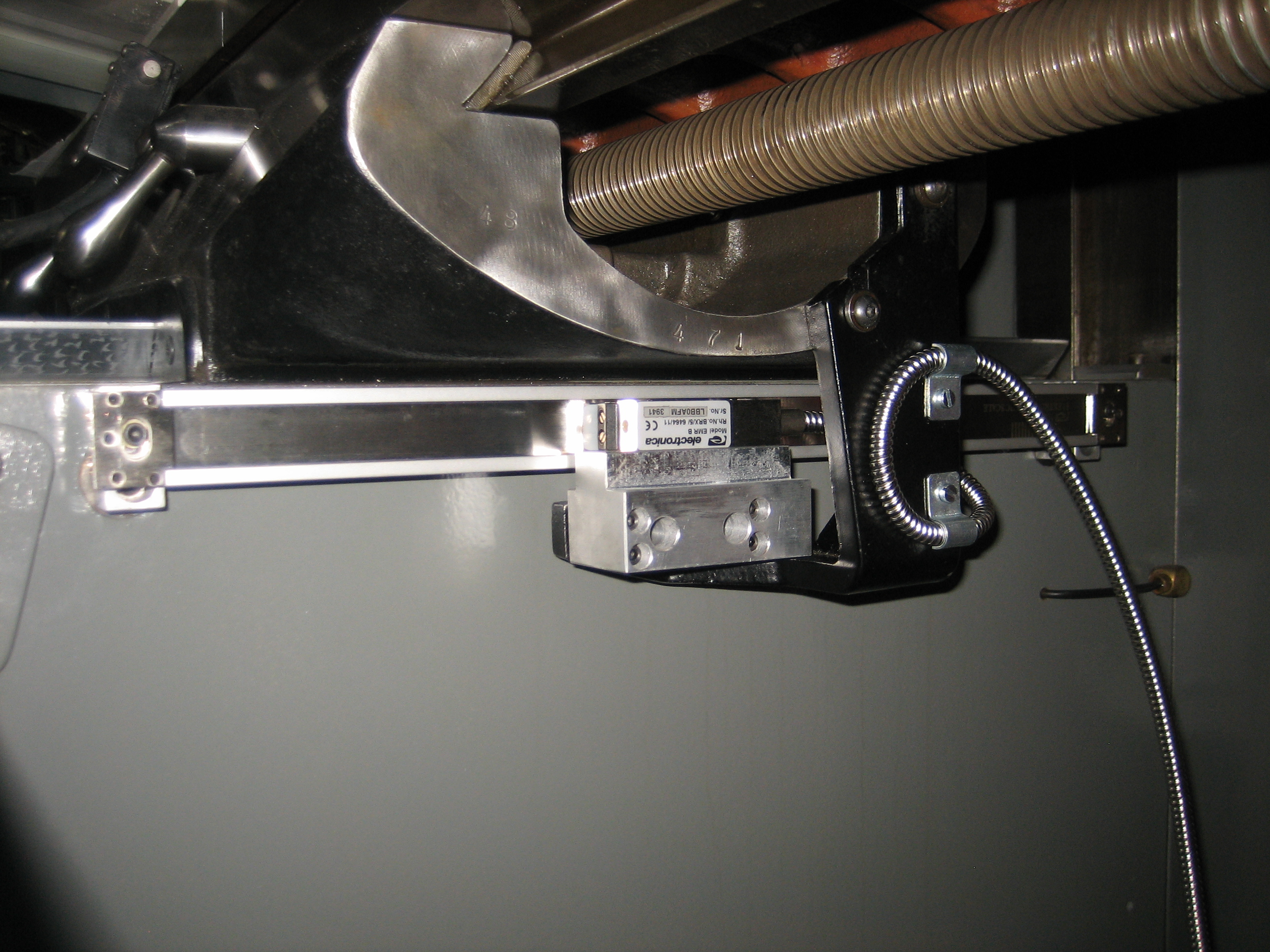
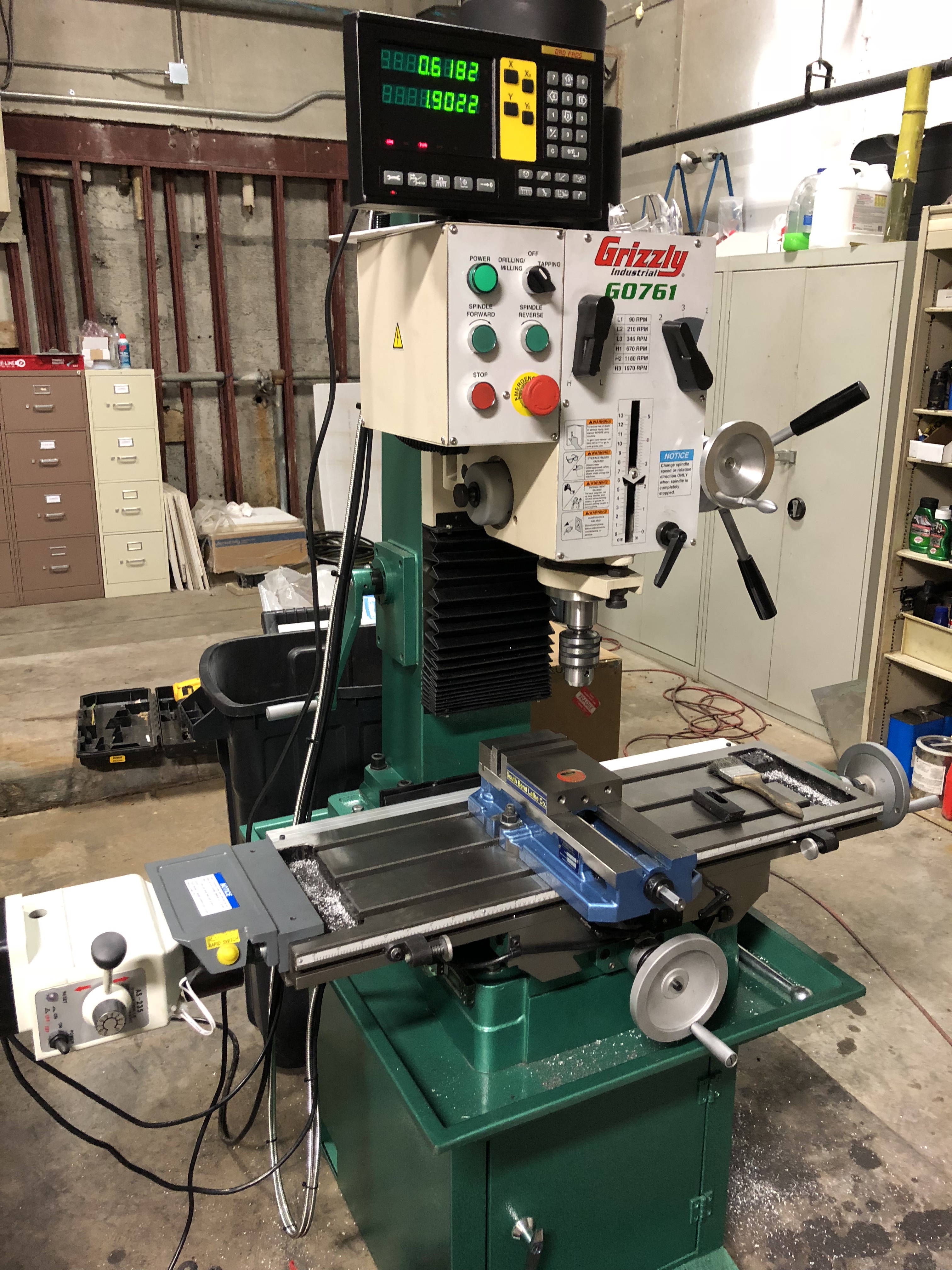
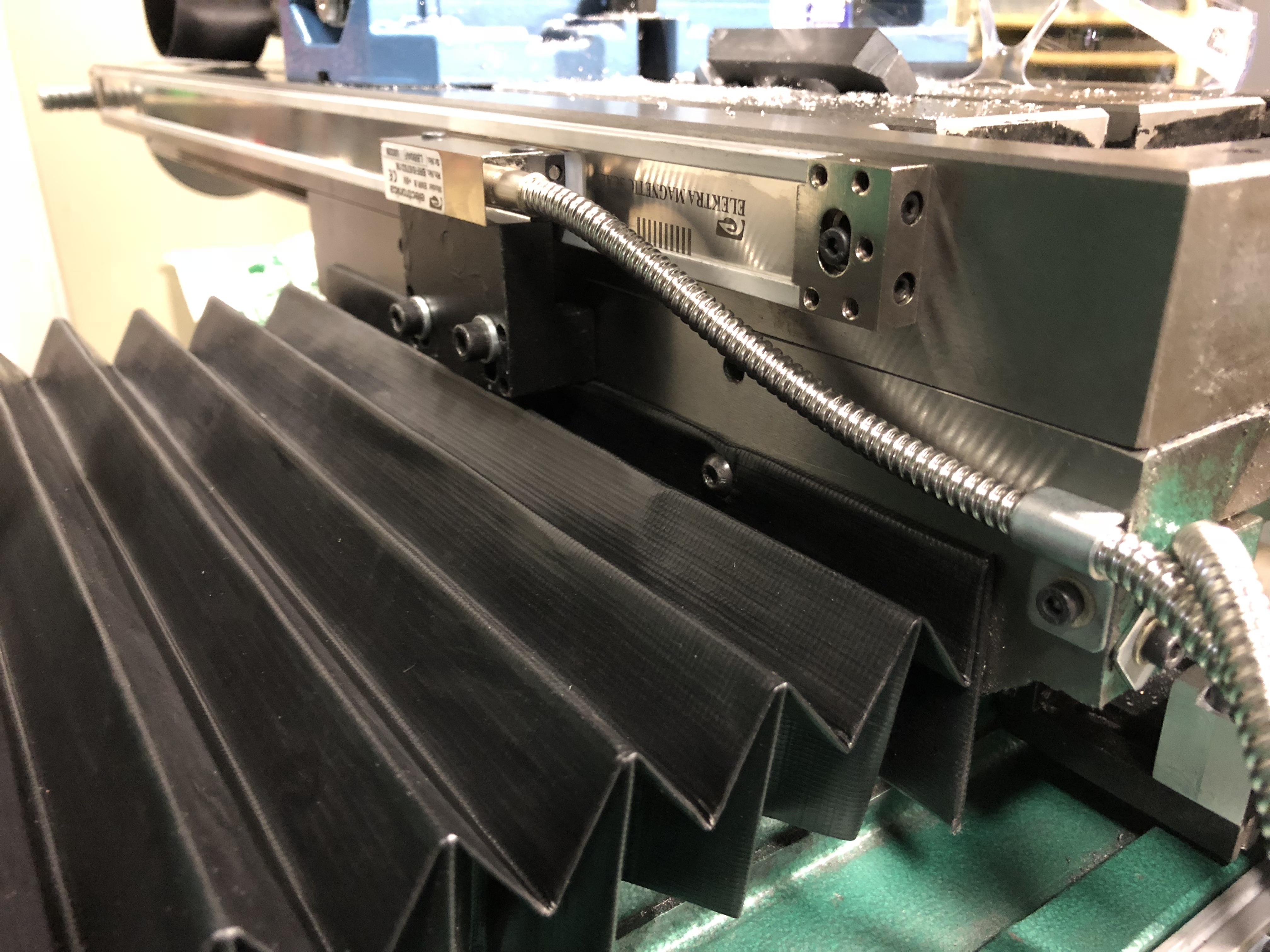
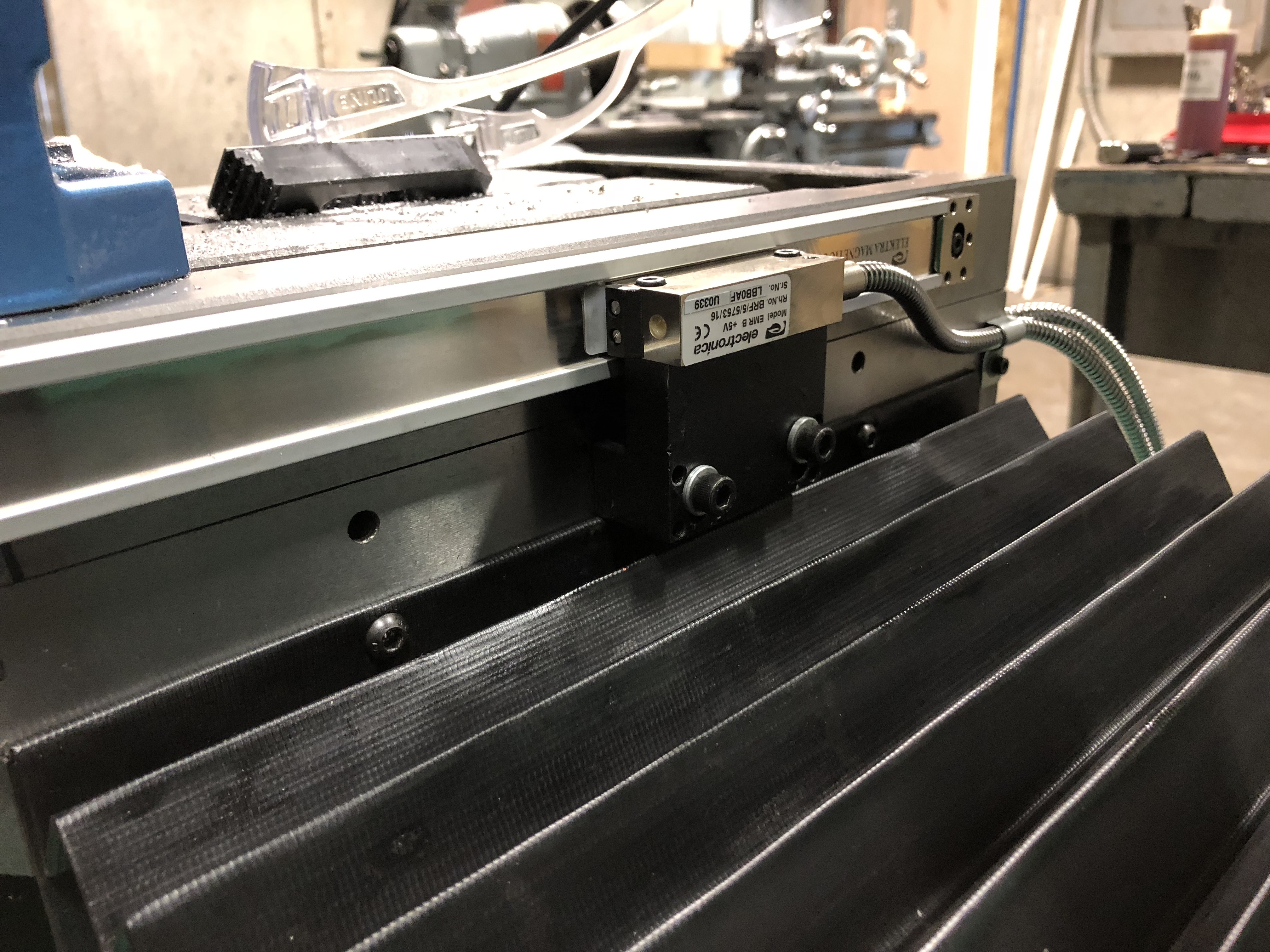
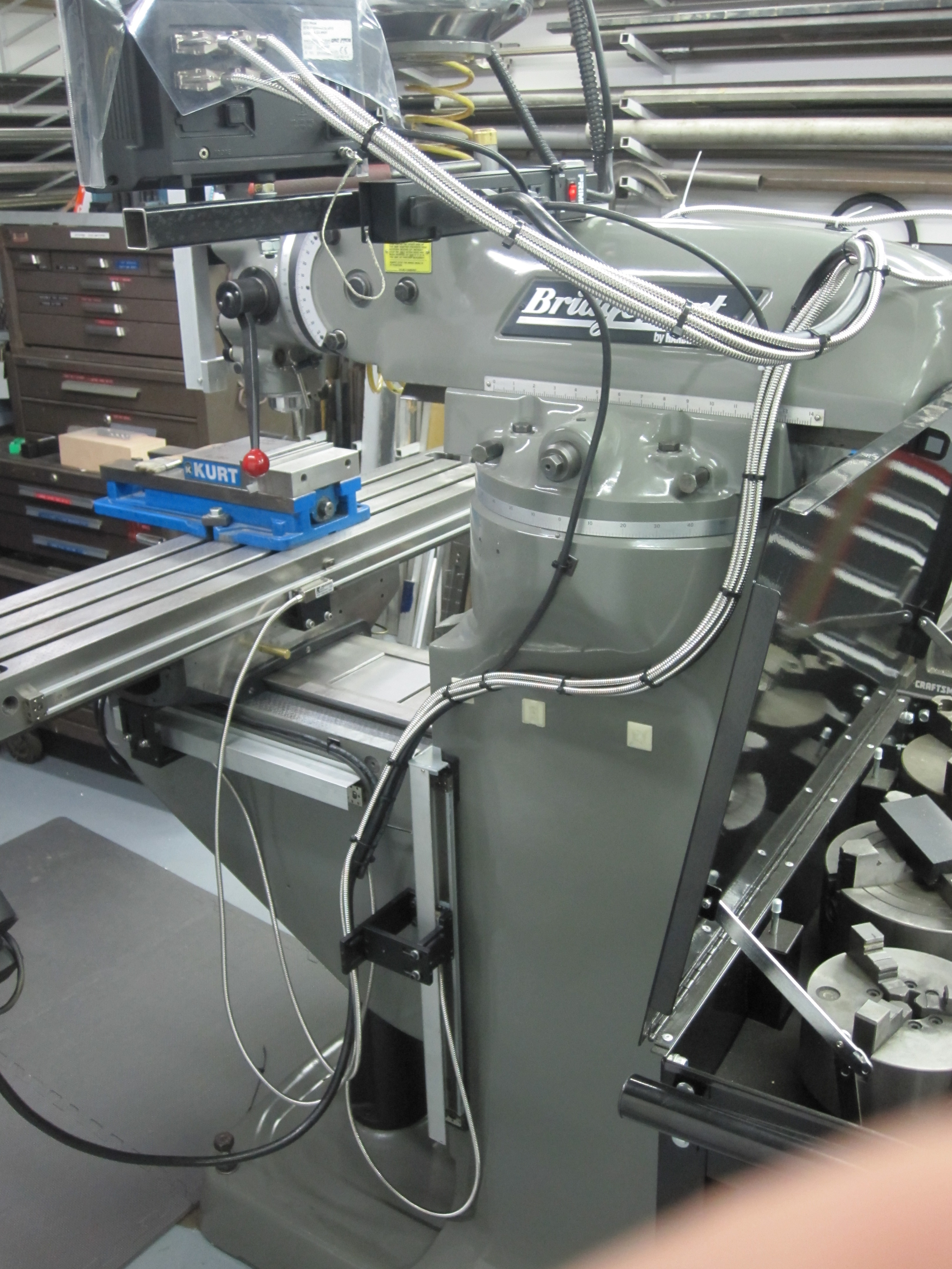
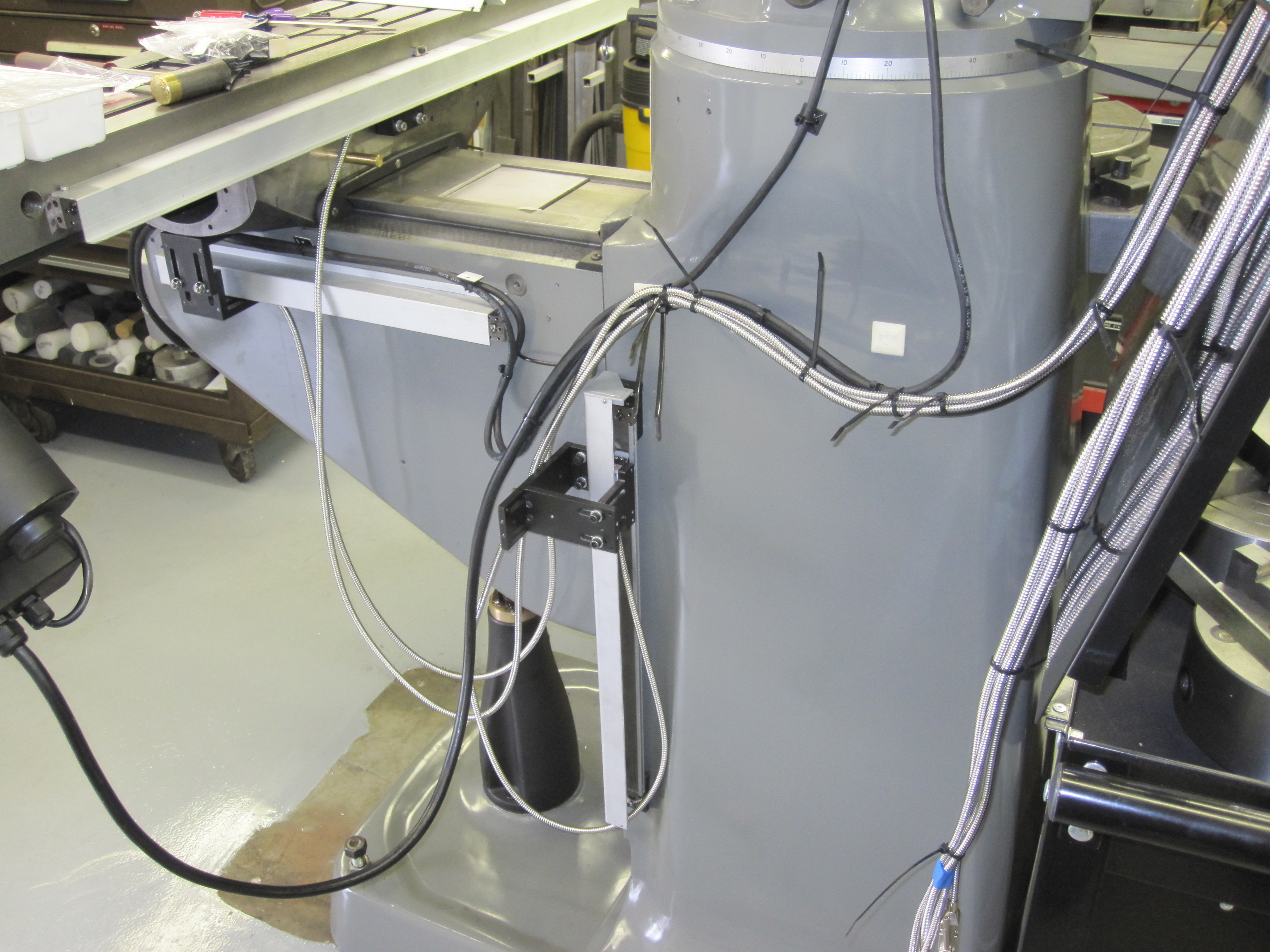
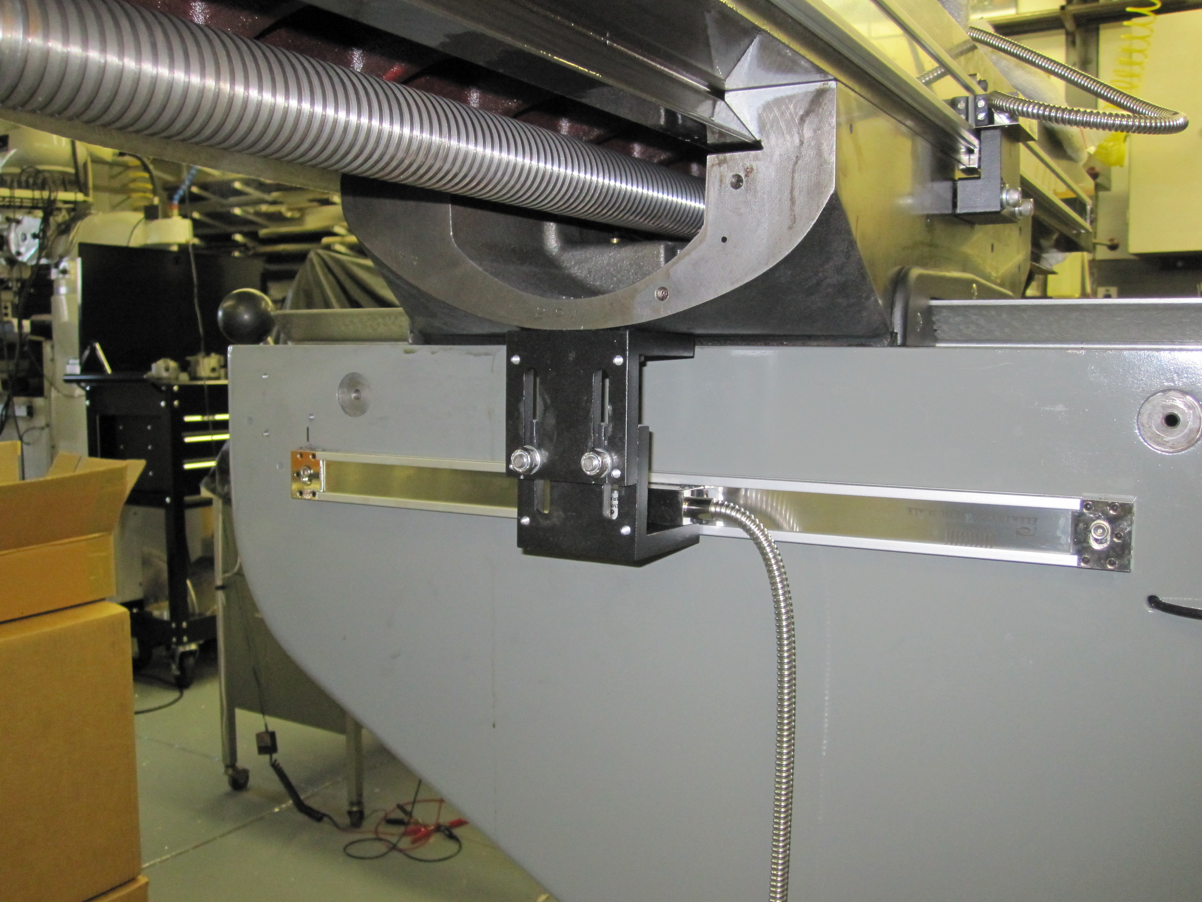
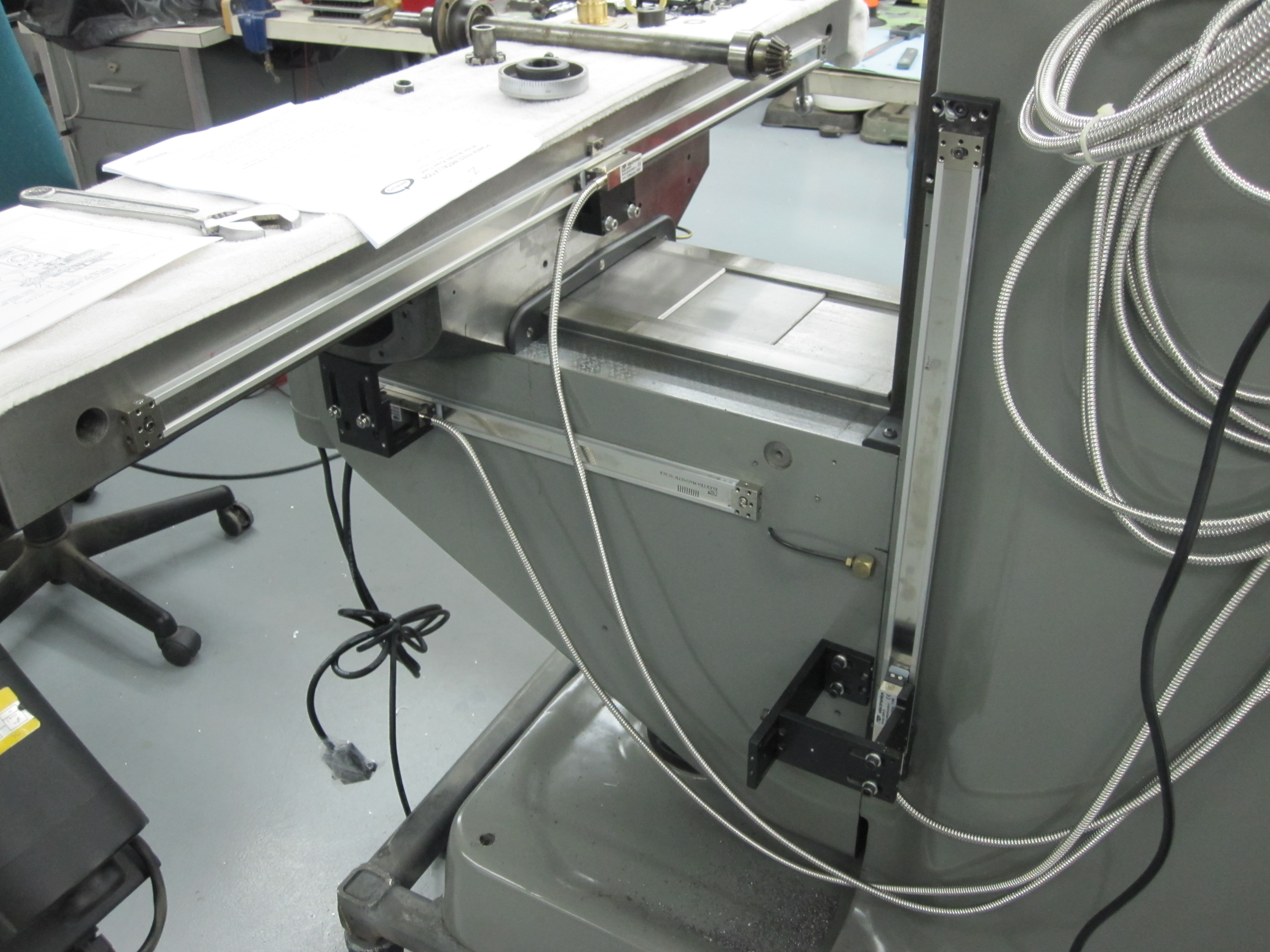
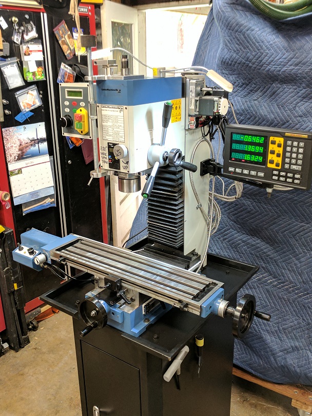
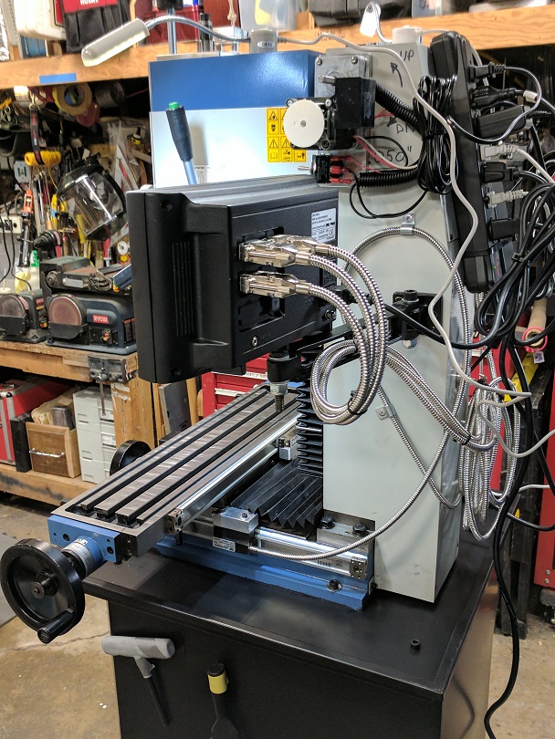
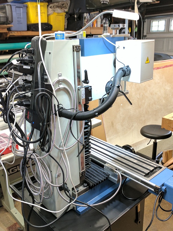
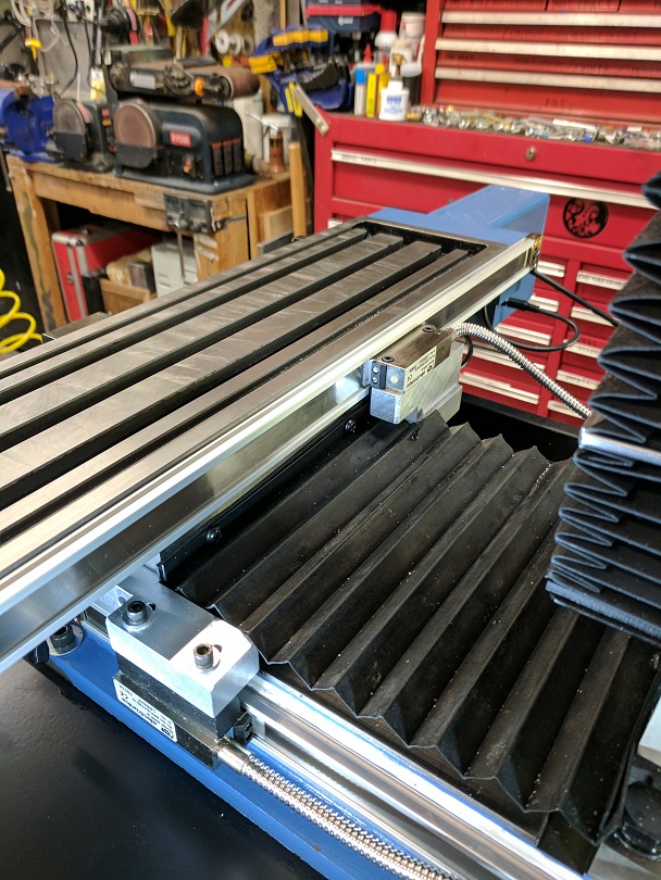
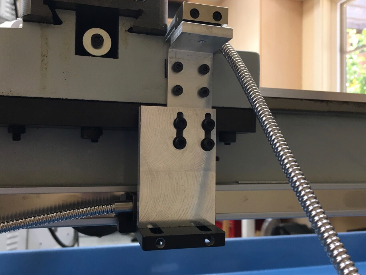
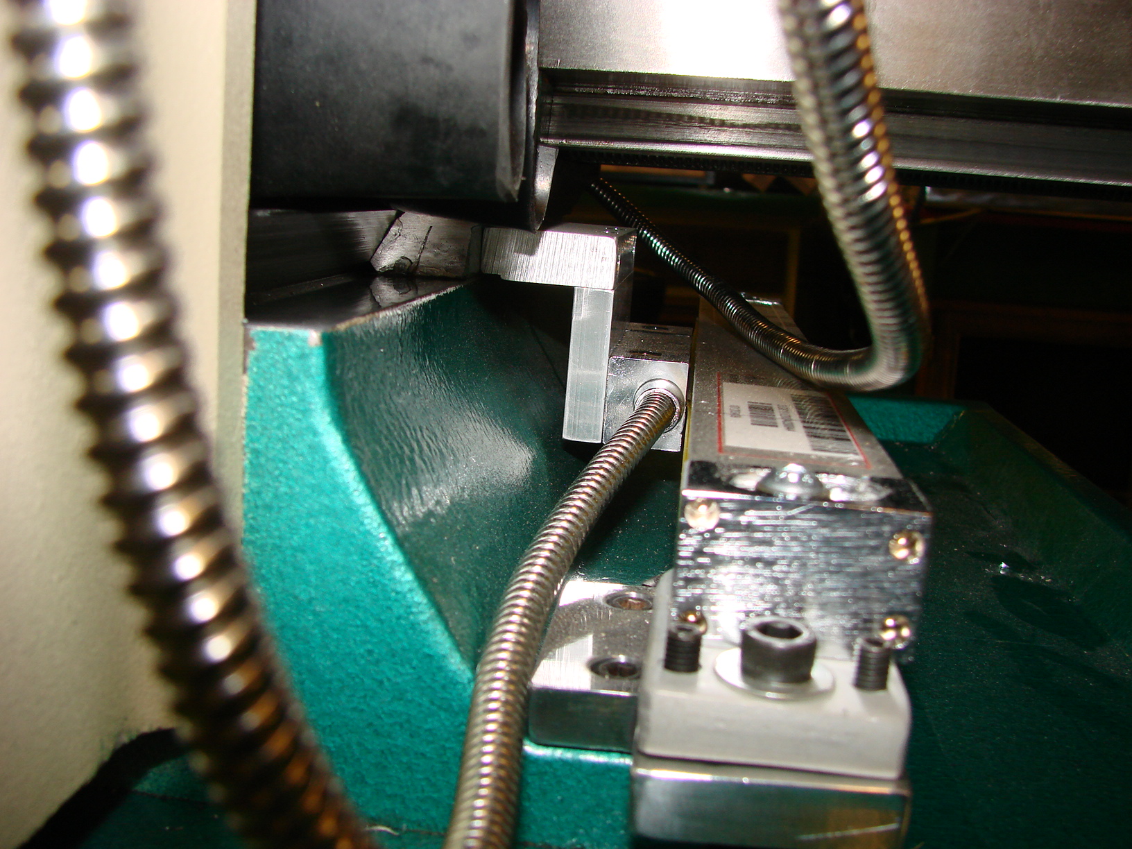
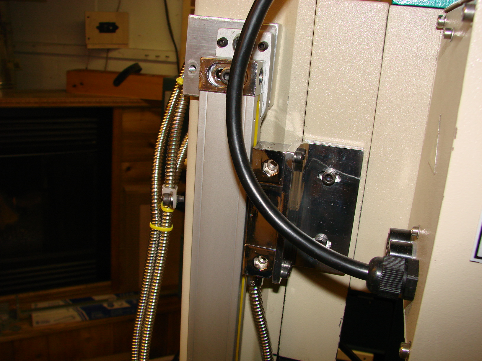
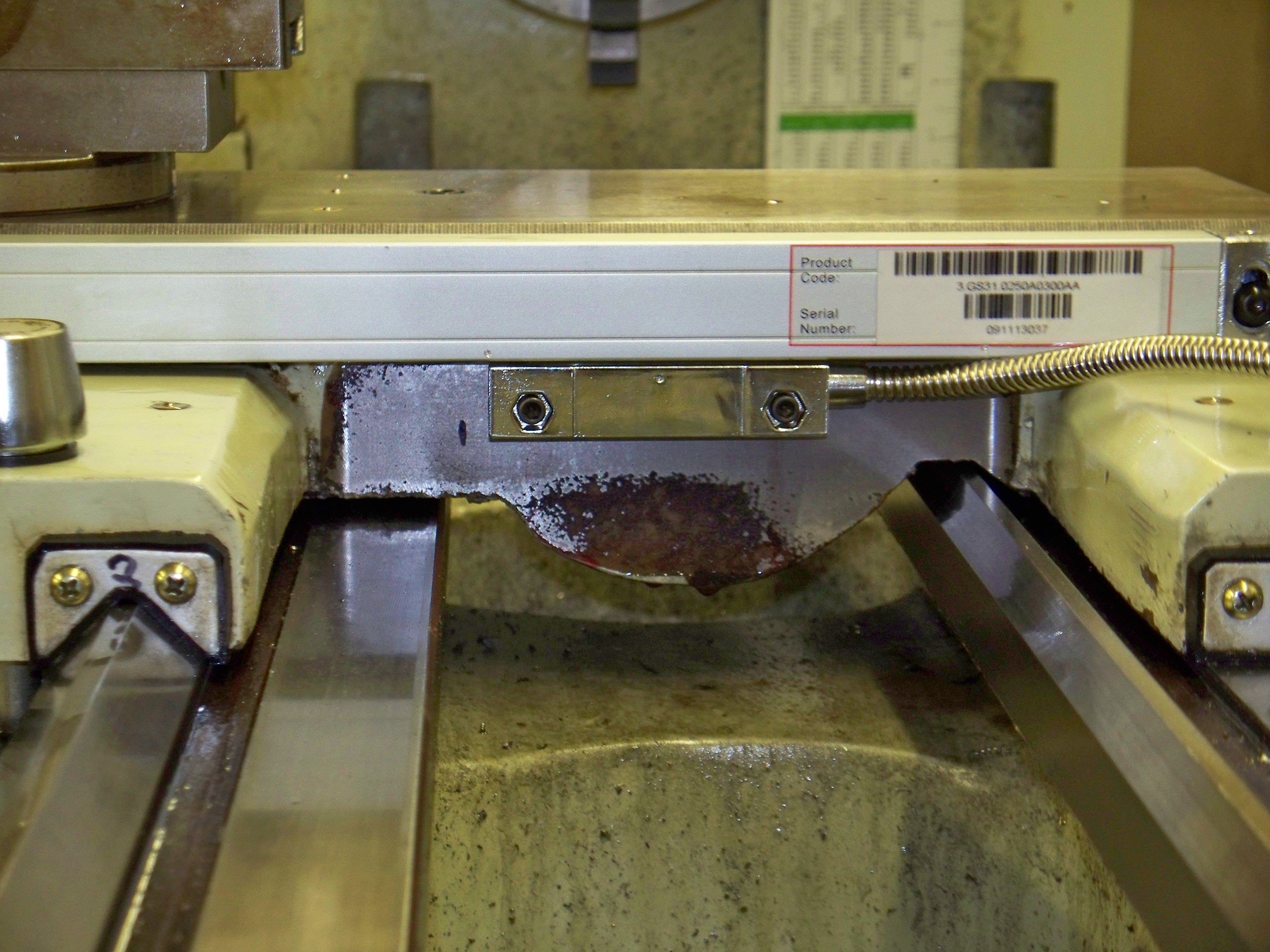
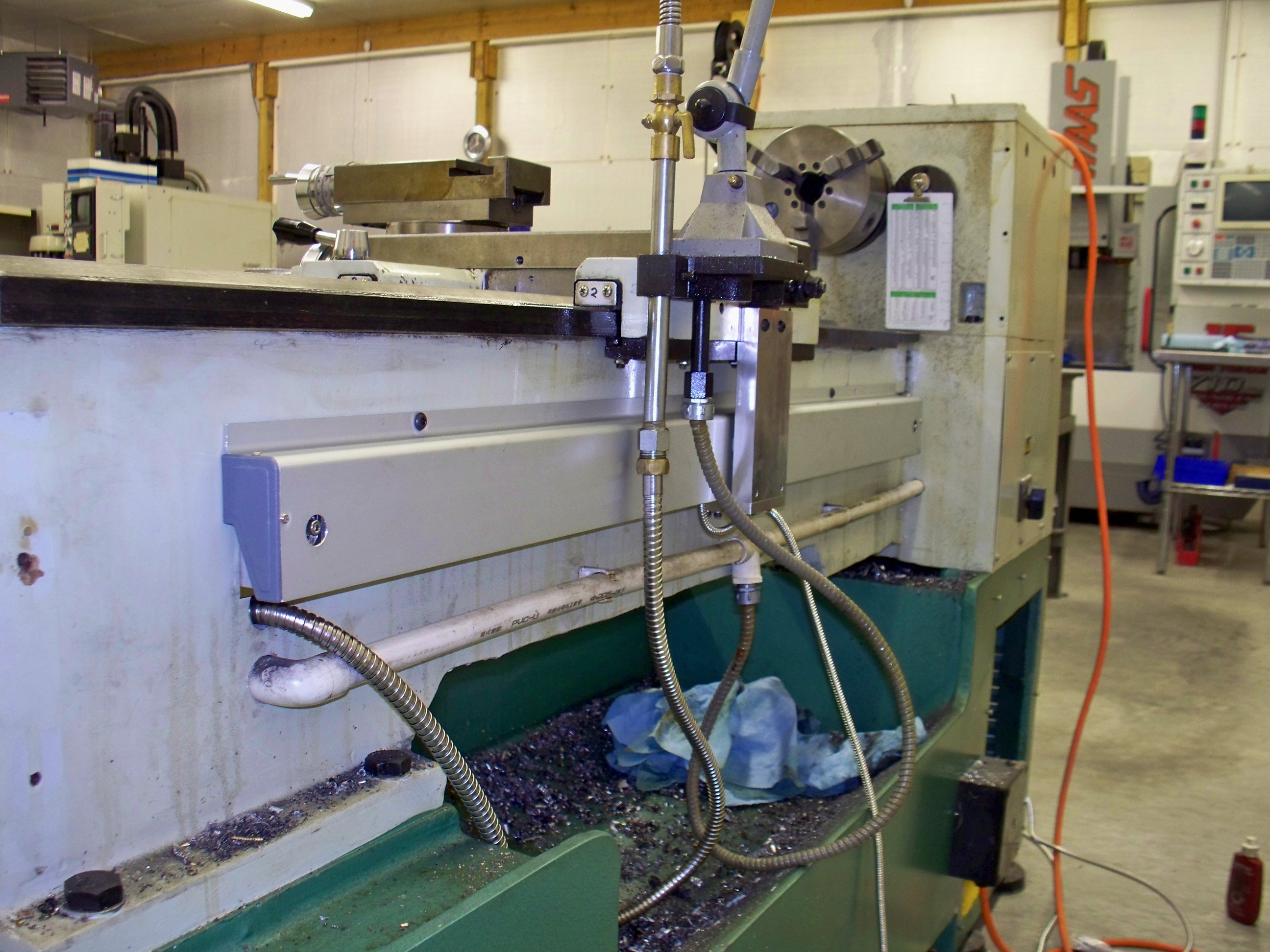
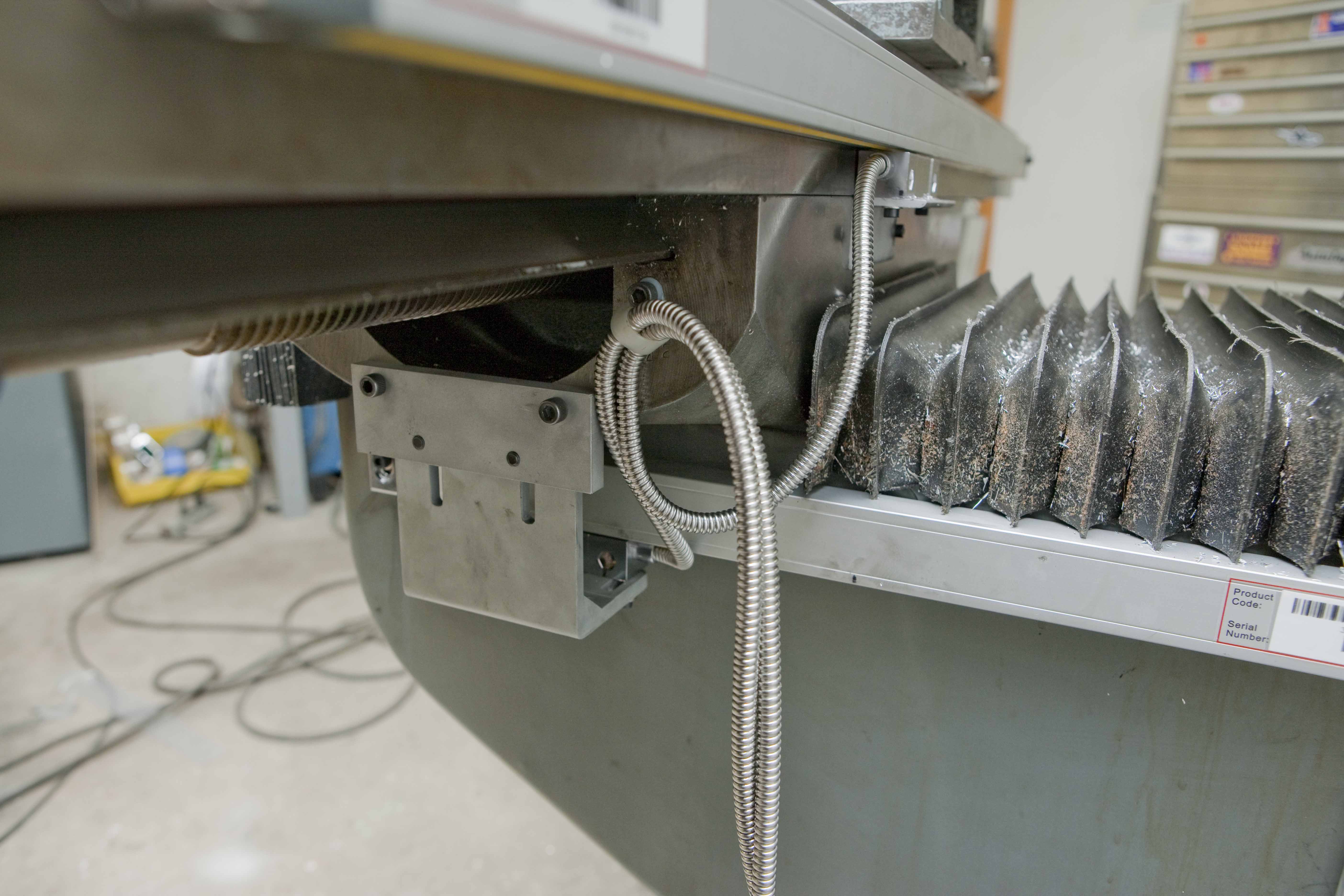
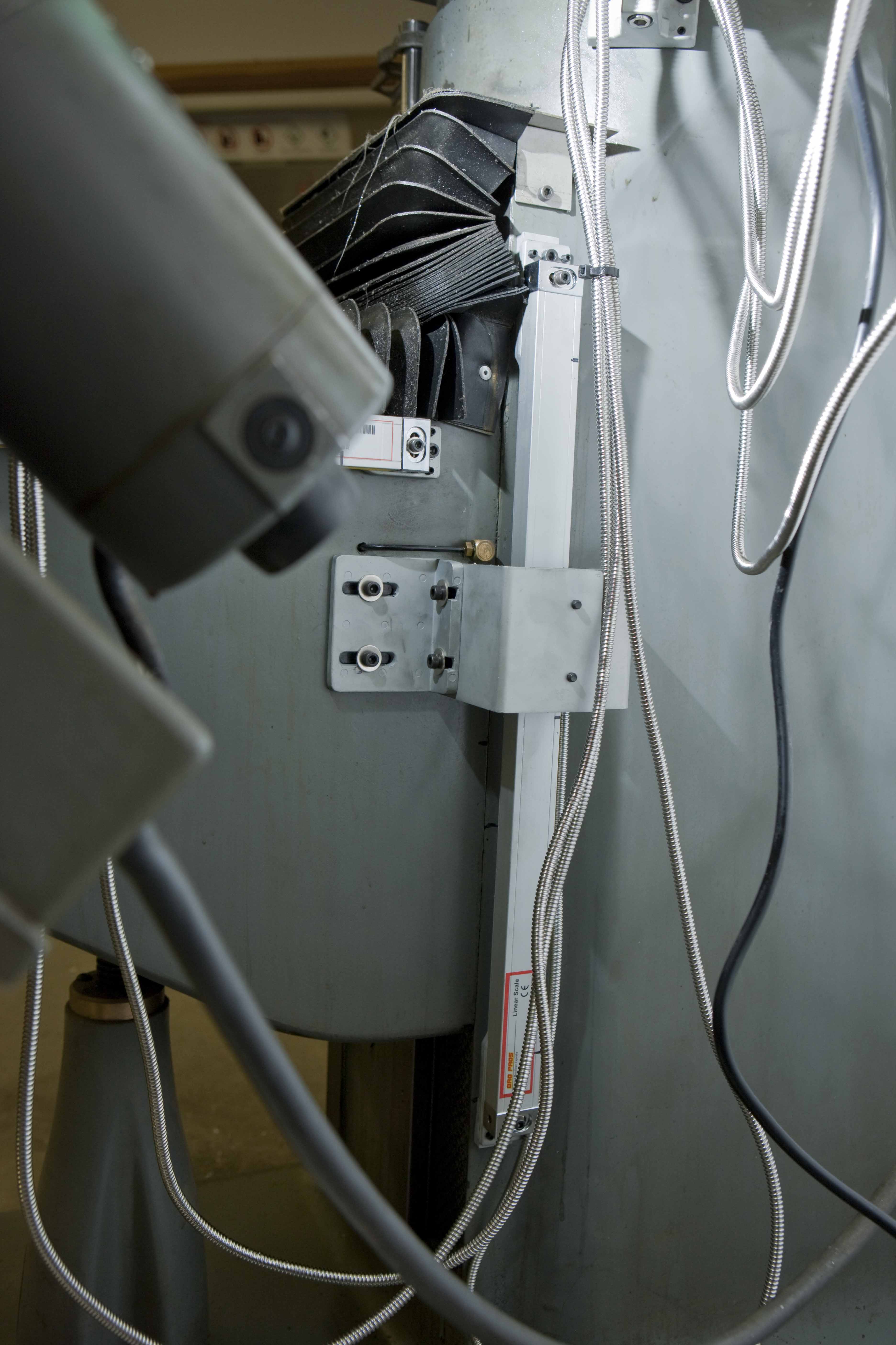
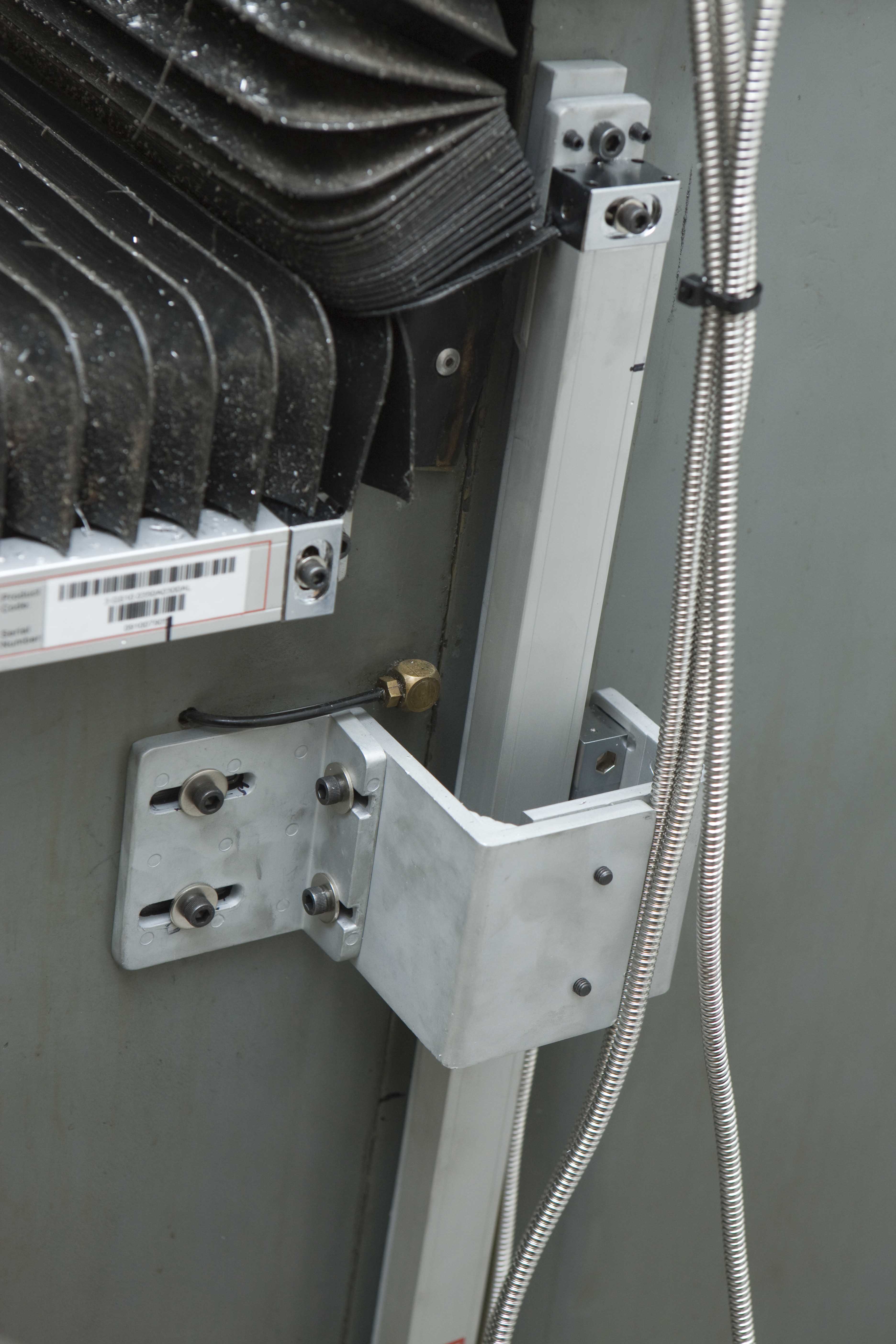
#4 - Courtesy
of T. Byrnhe with a 3 Axis EL700 Magnetic Scale
Kit:
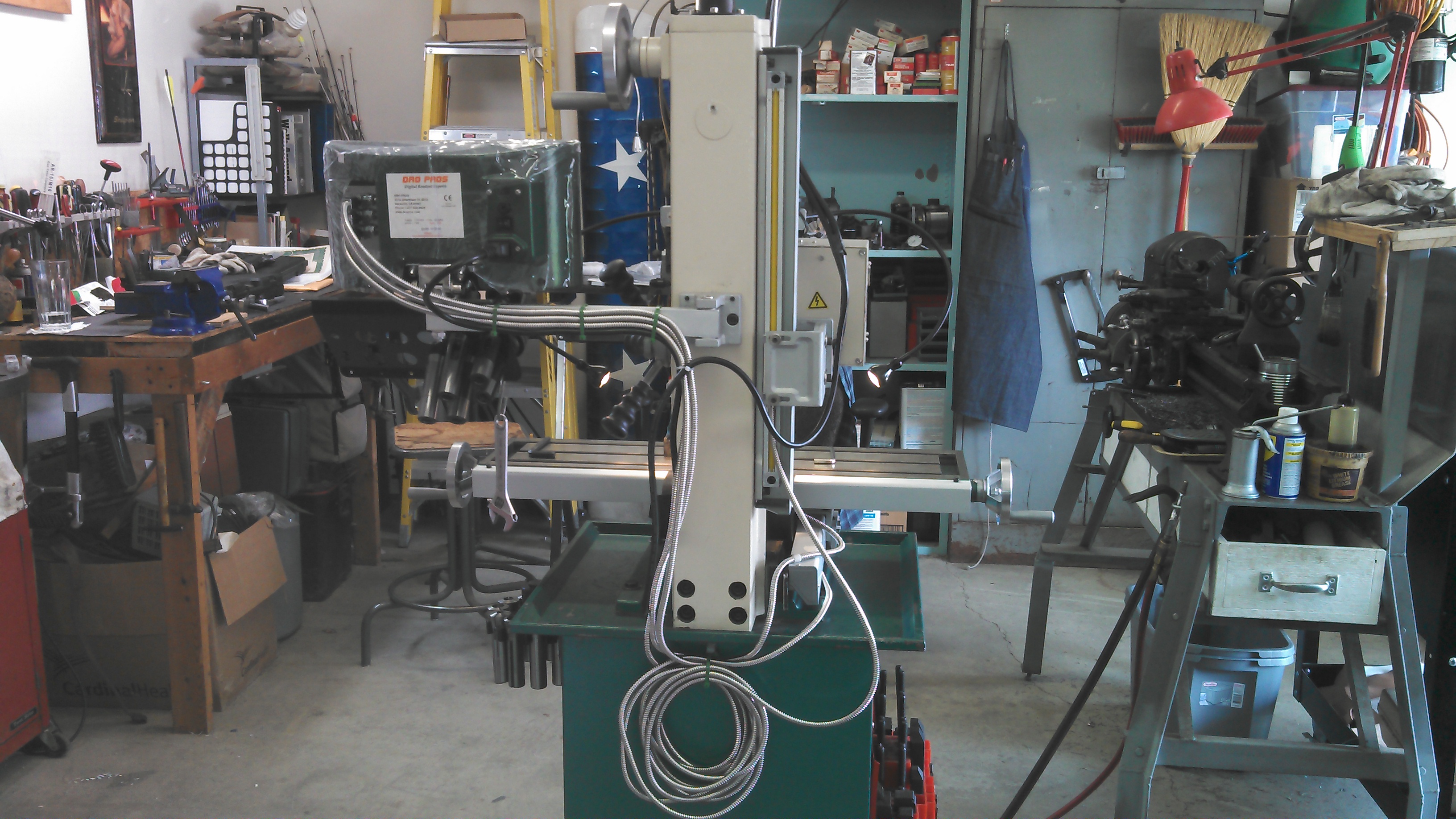
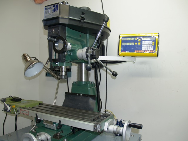
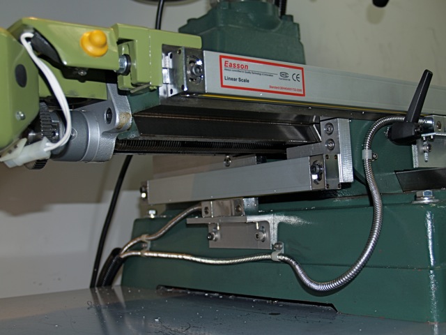
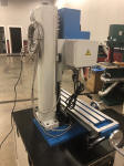
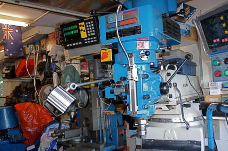
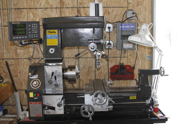
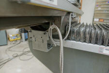
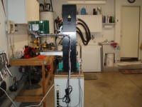
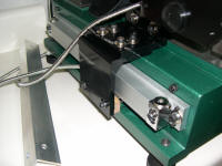
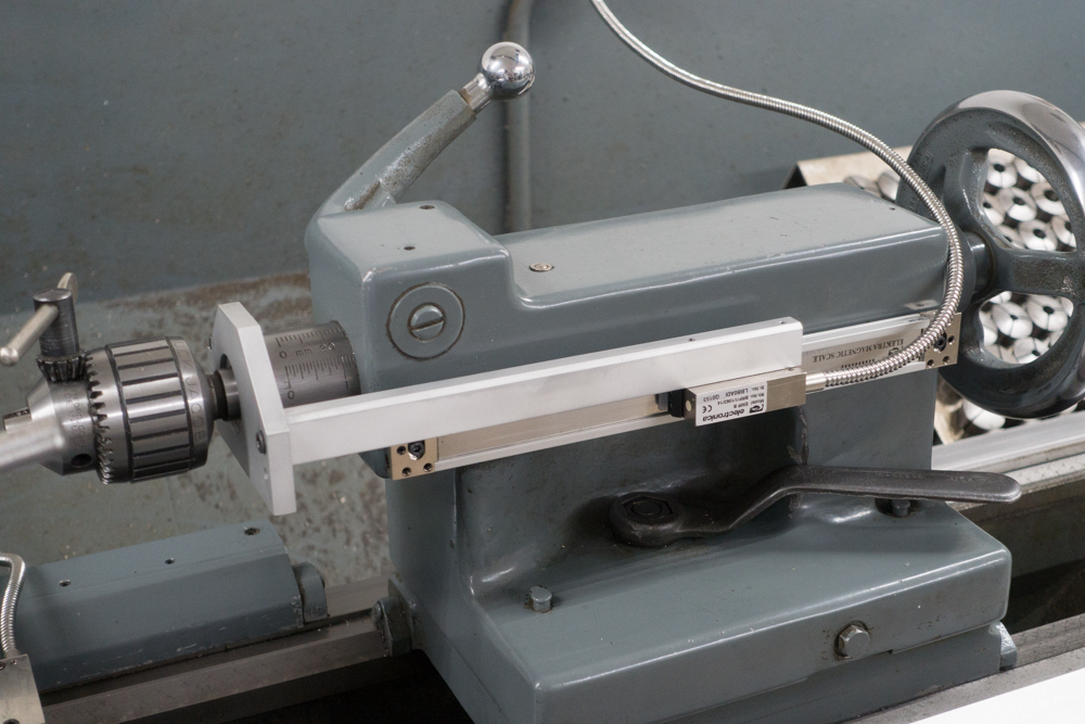
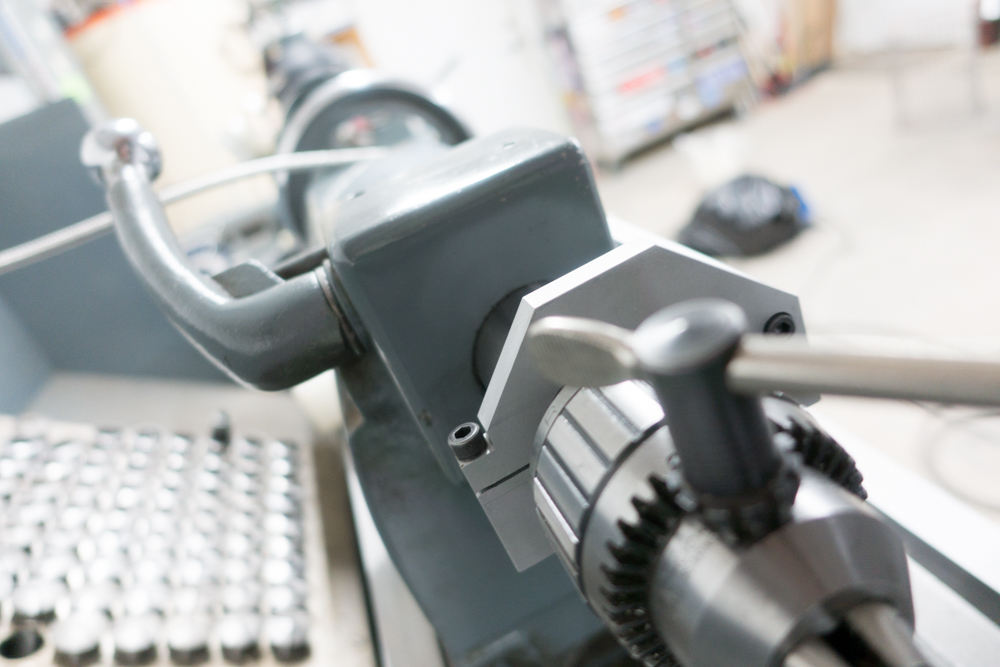
#5 - Courtesy
of R. Humphreys with a 4 Axis EL700 Magnetic Scale
Kit:
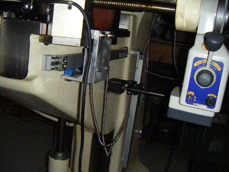
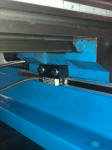
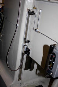
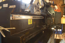
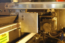
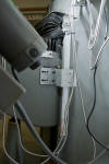
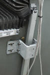
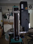
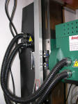
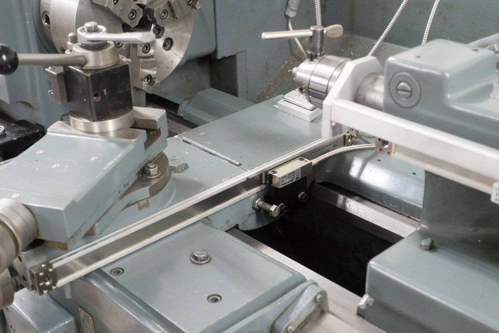
#6 - Courtesy
of C. Bennett with a 3 Axis EL700 Magnetic Scale
Kit:

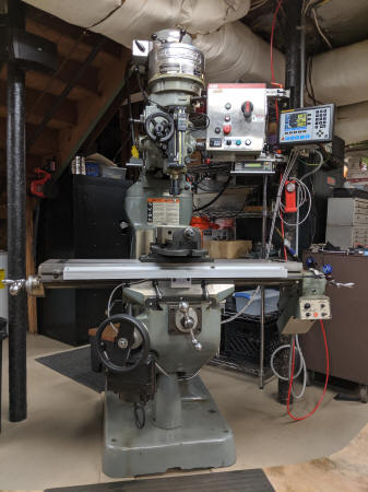
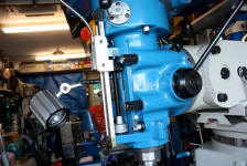
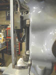
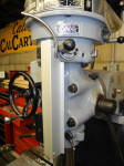
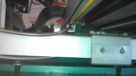
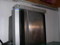
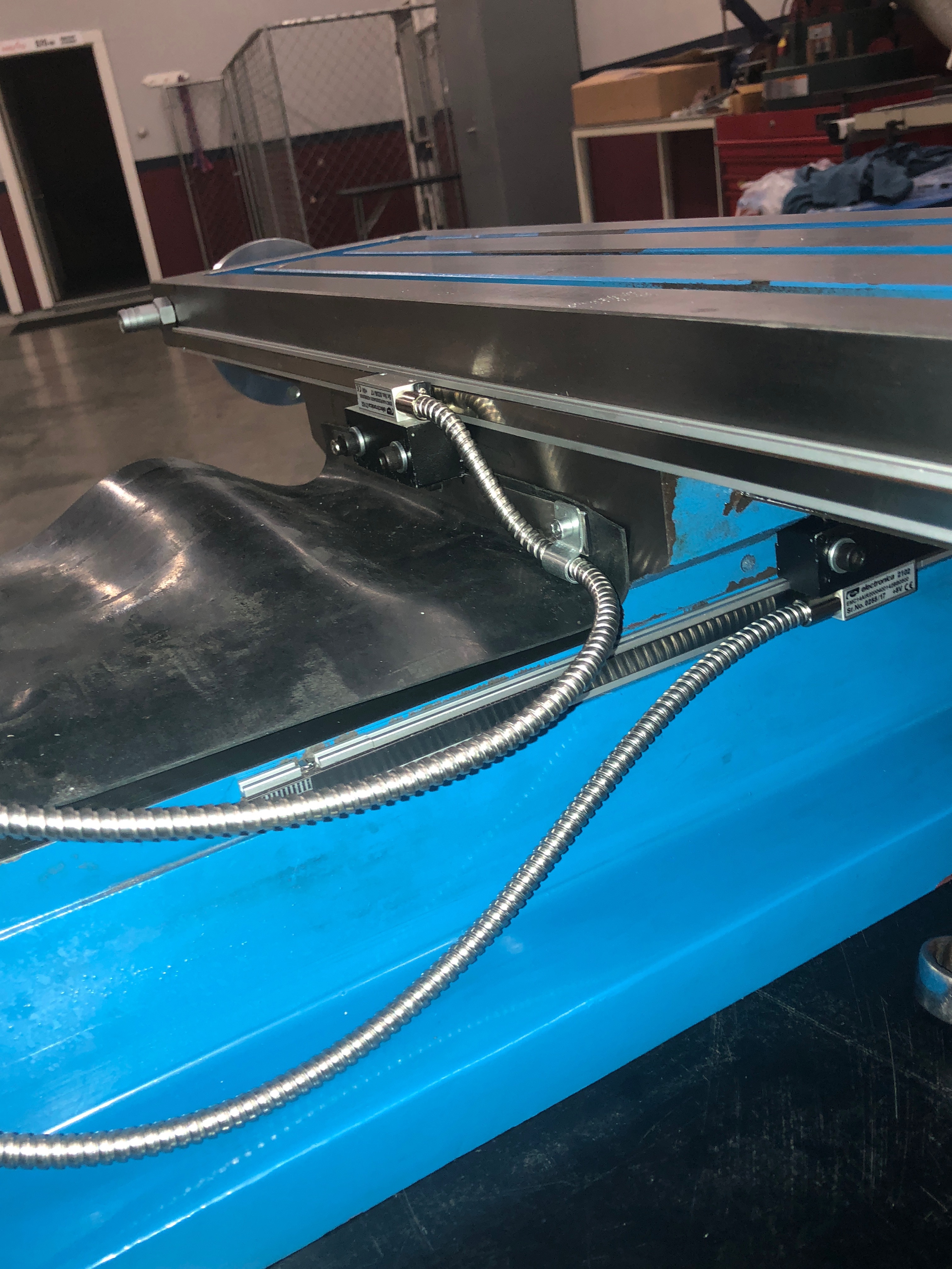
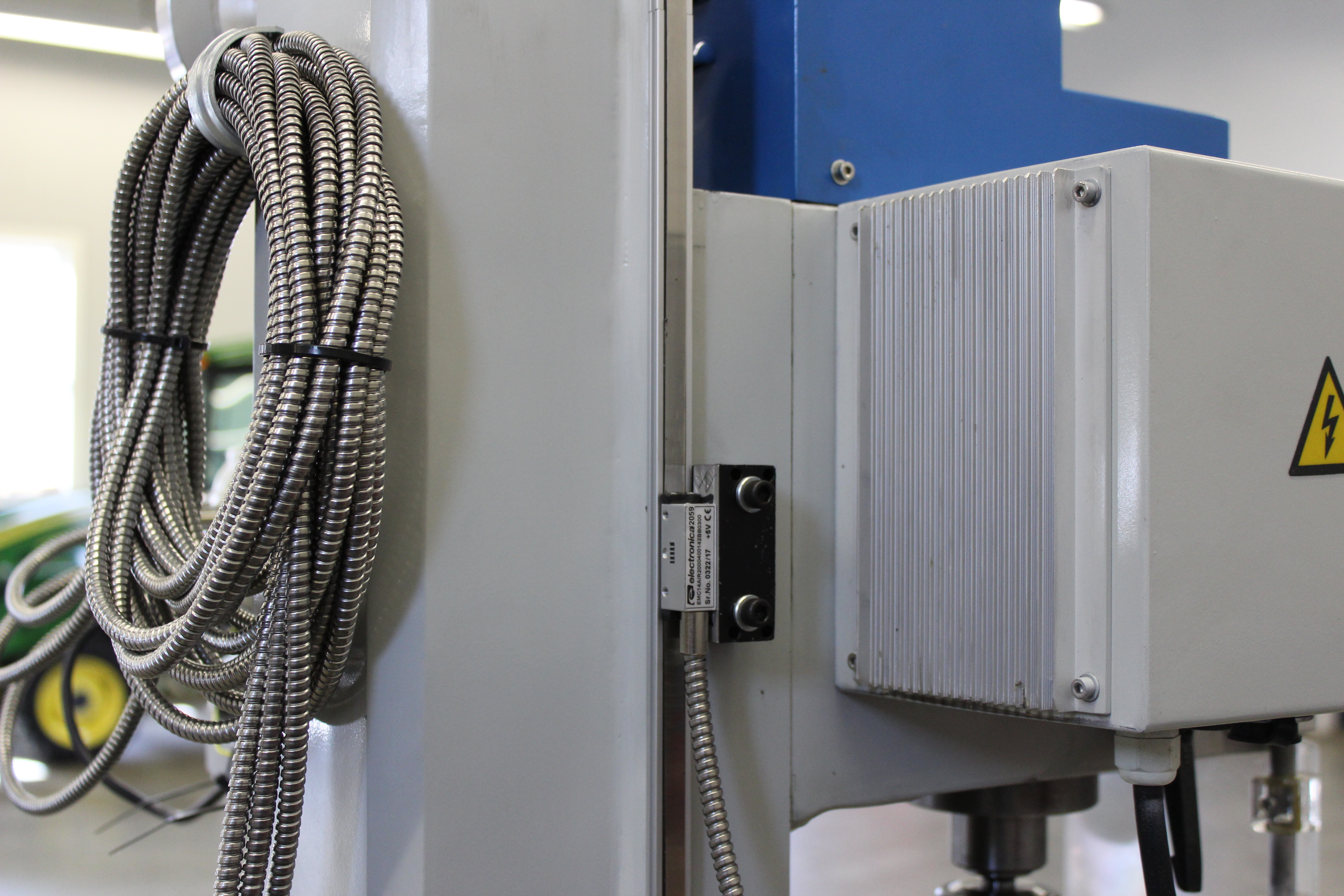
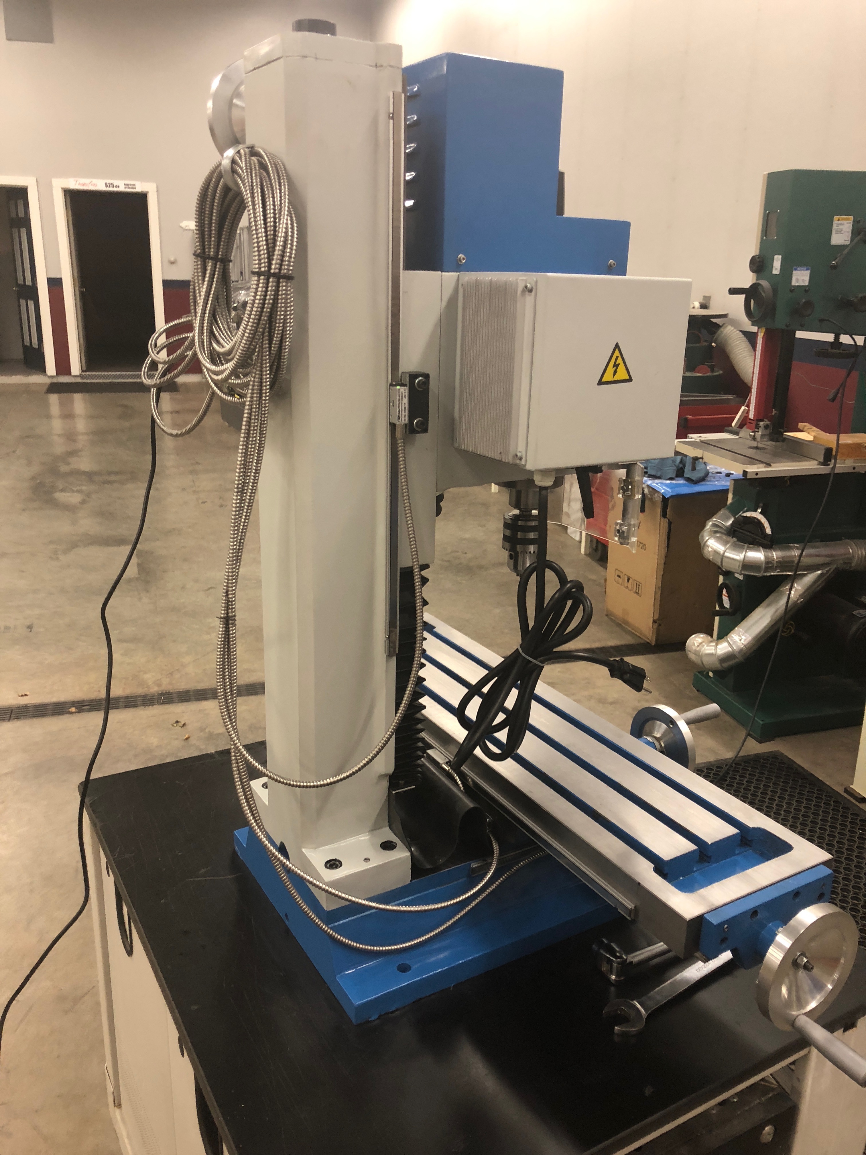
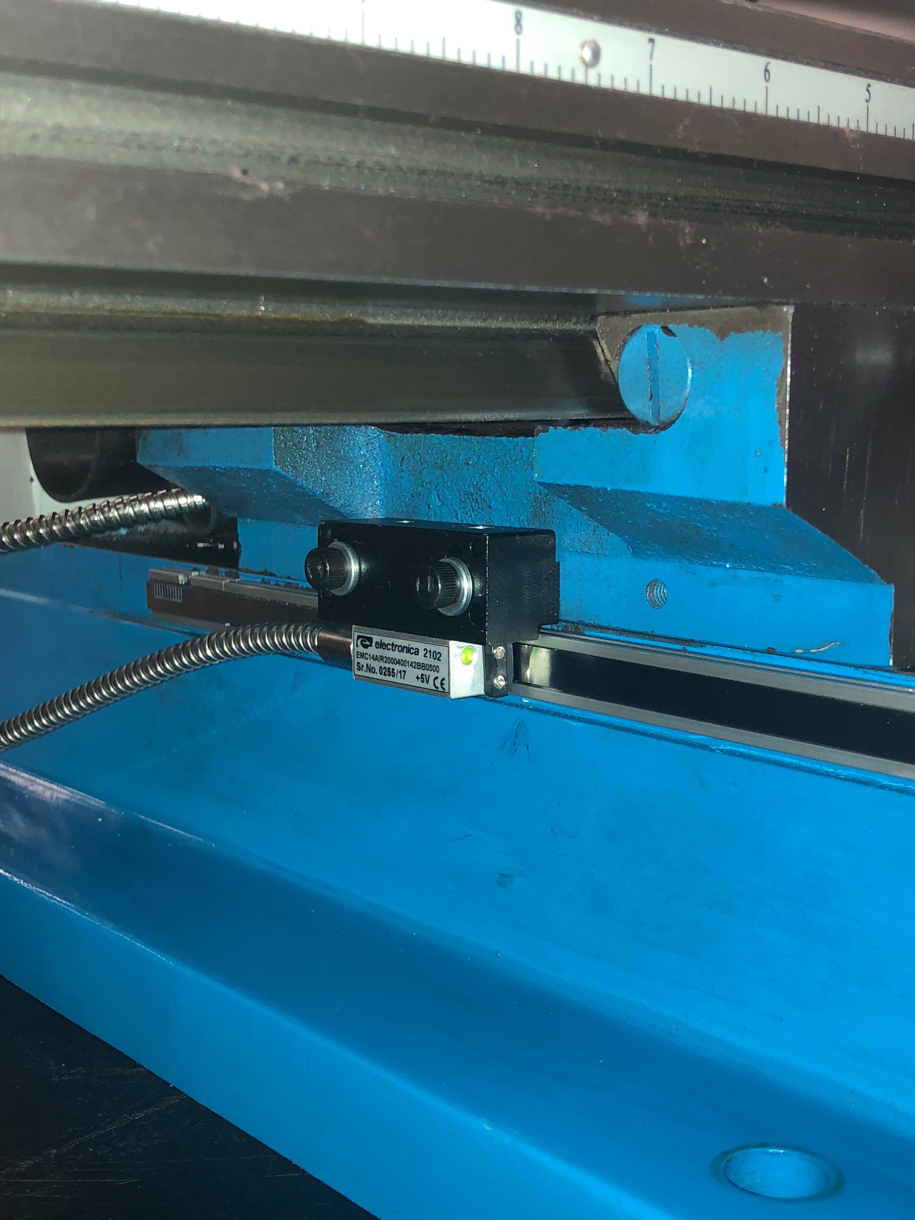
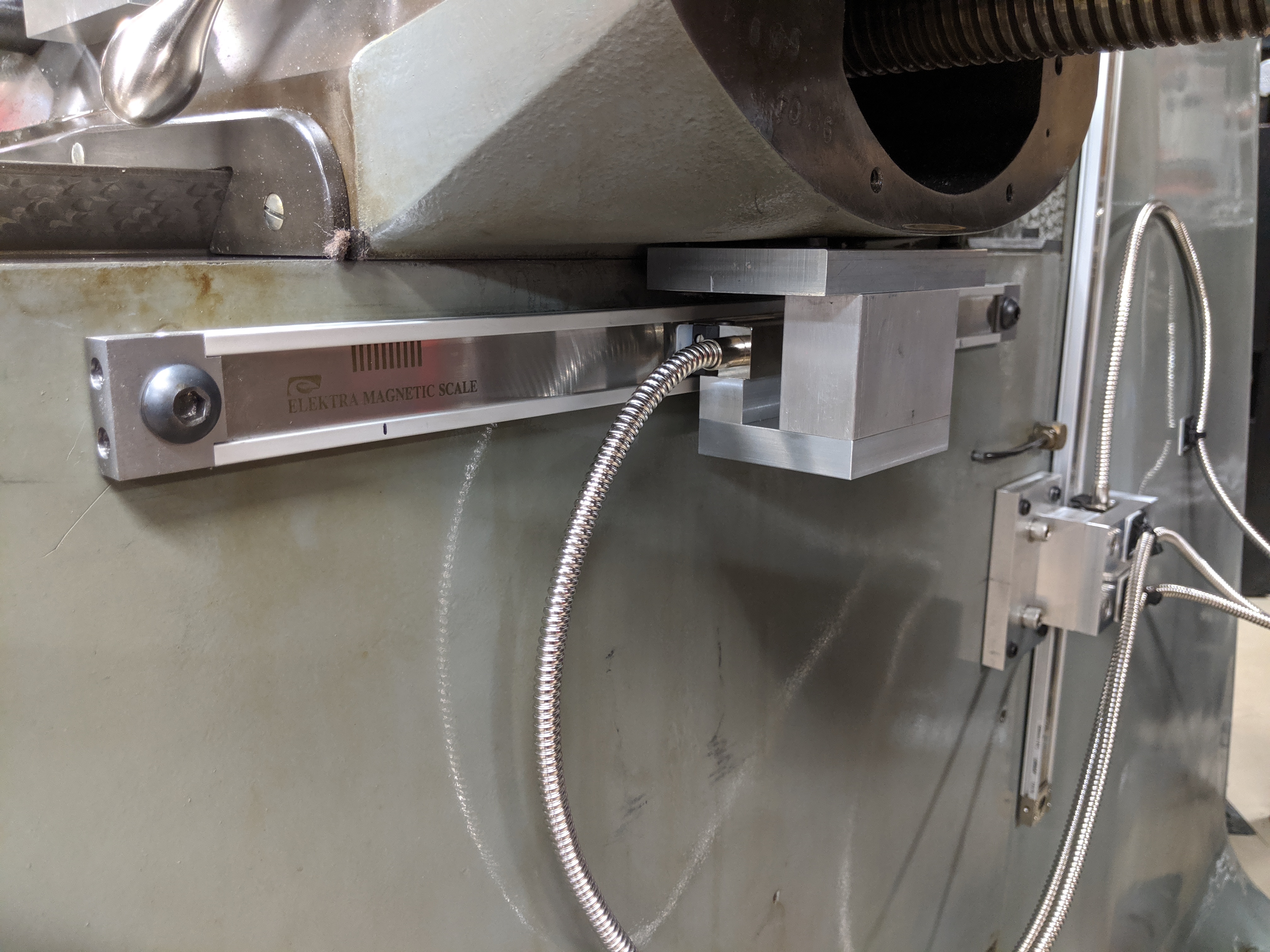
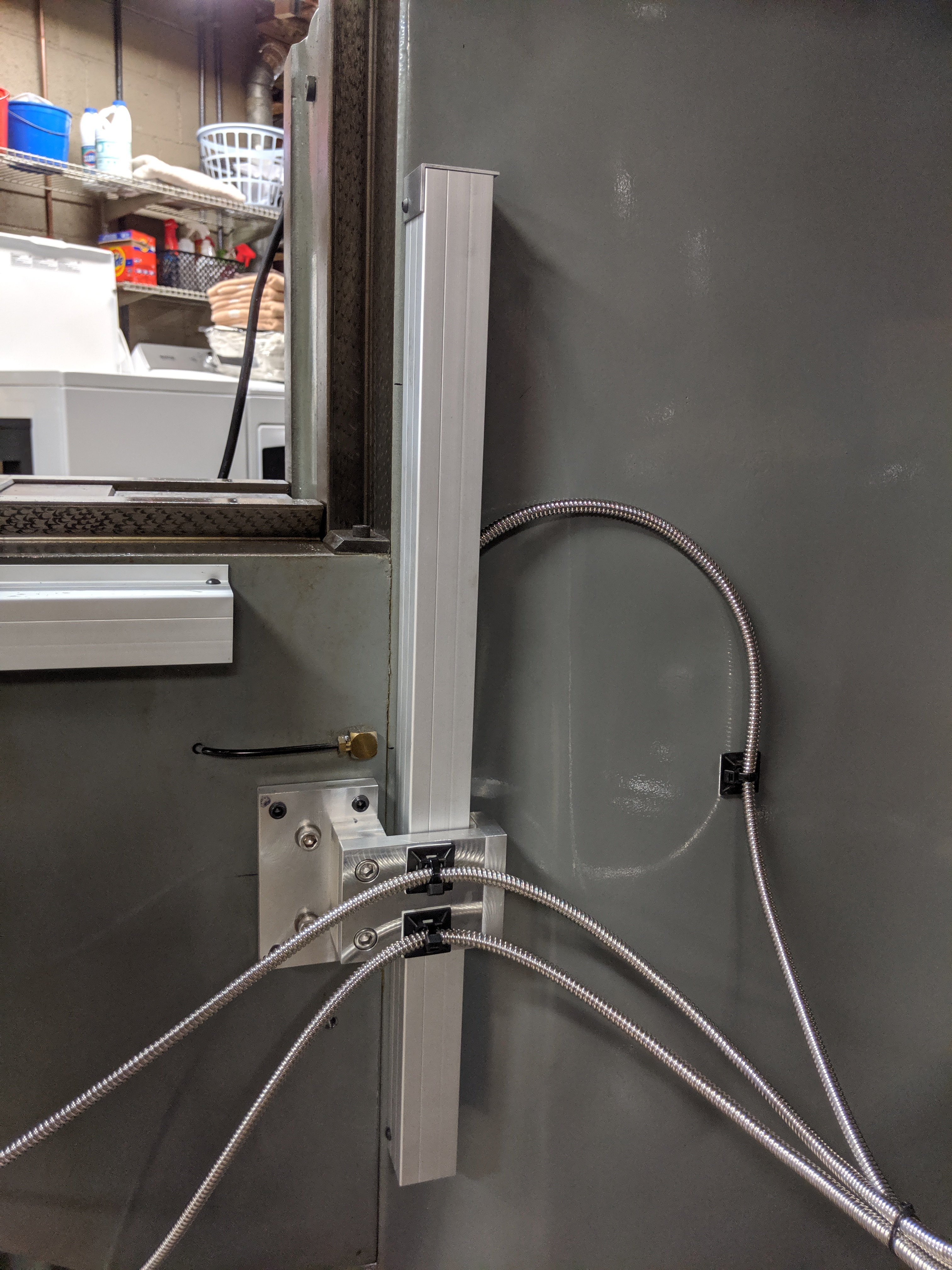
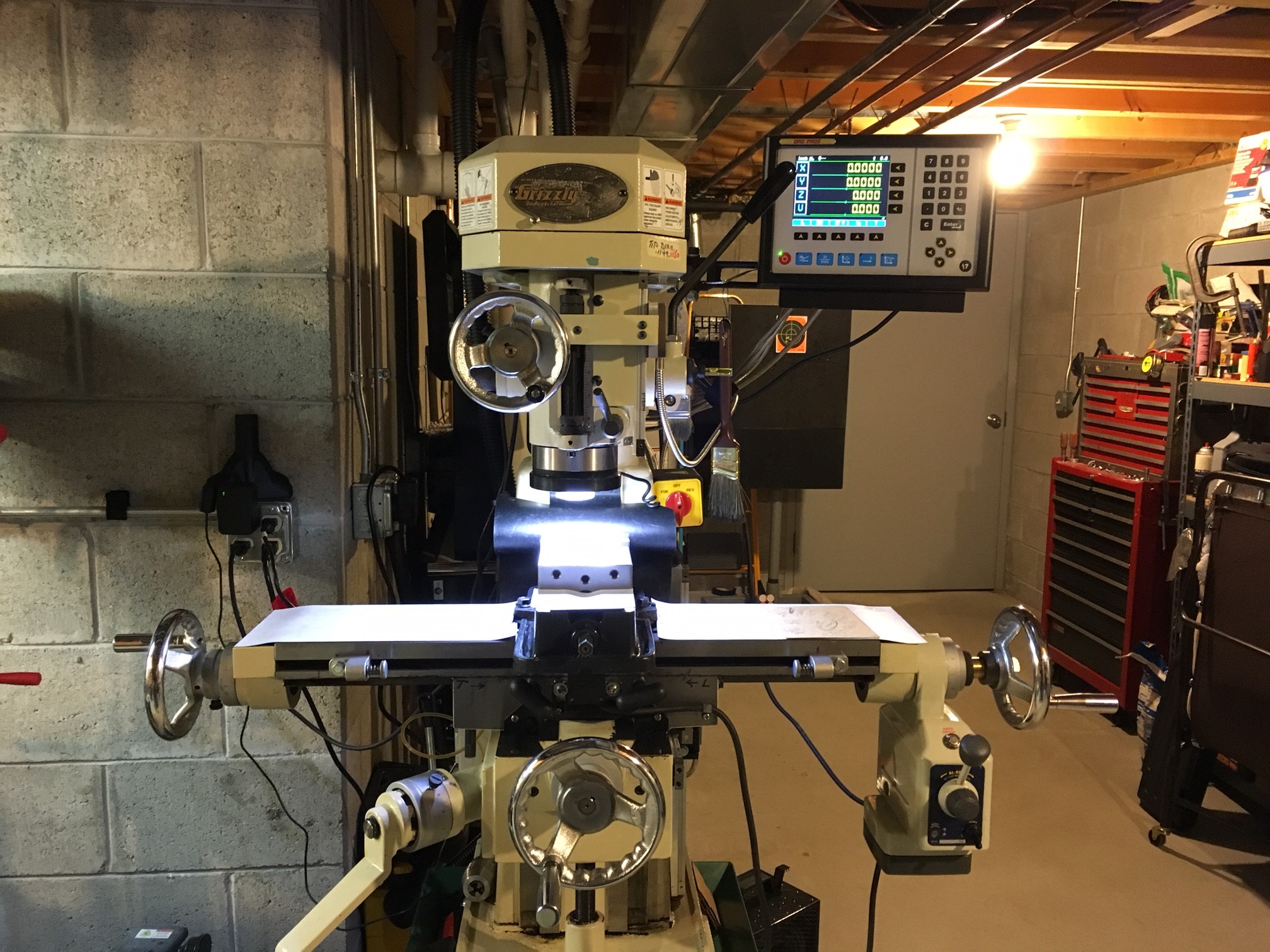
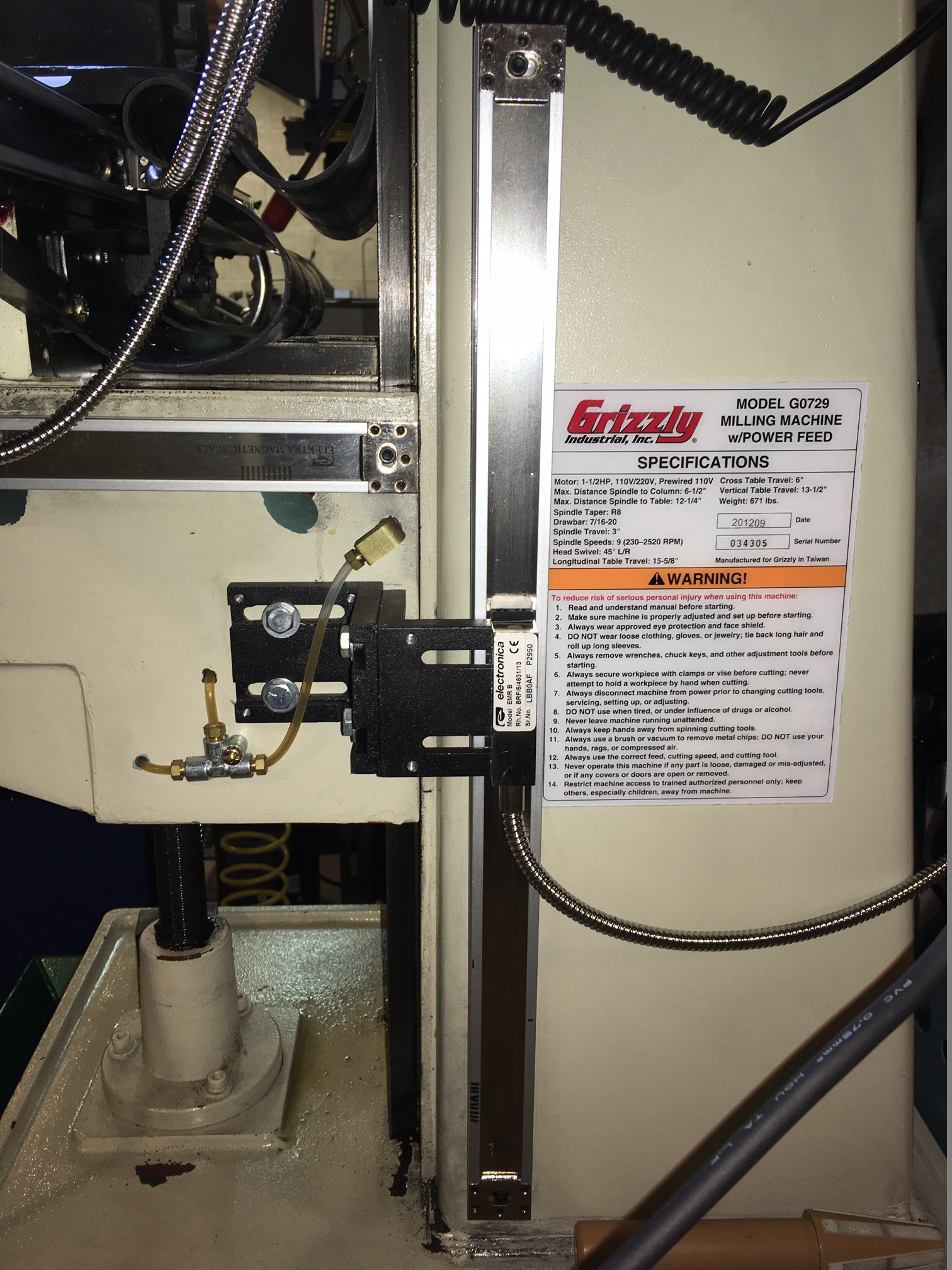
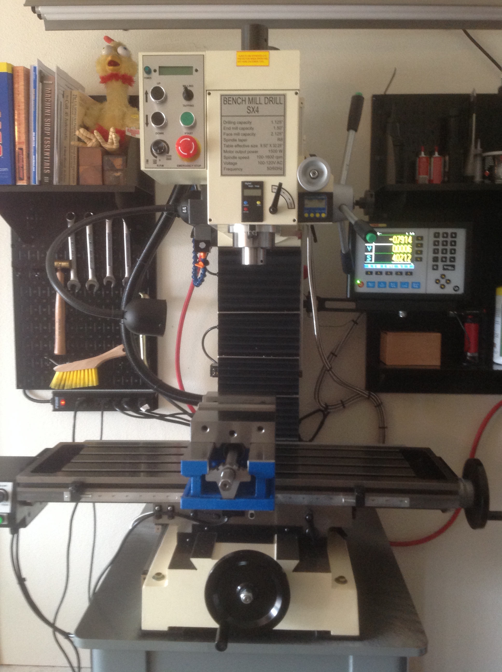
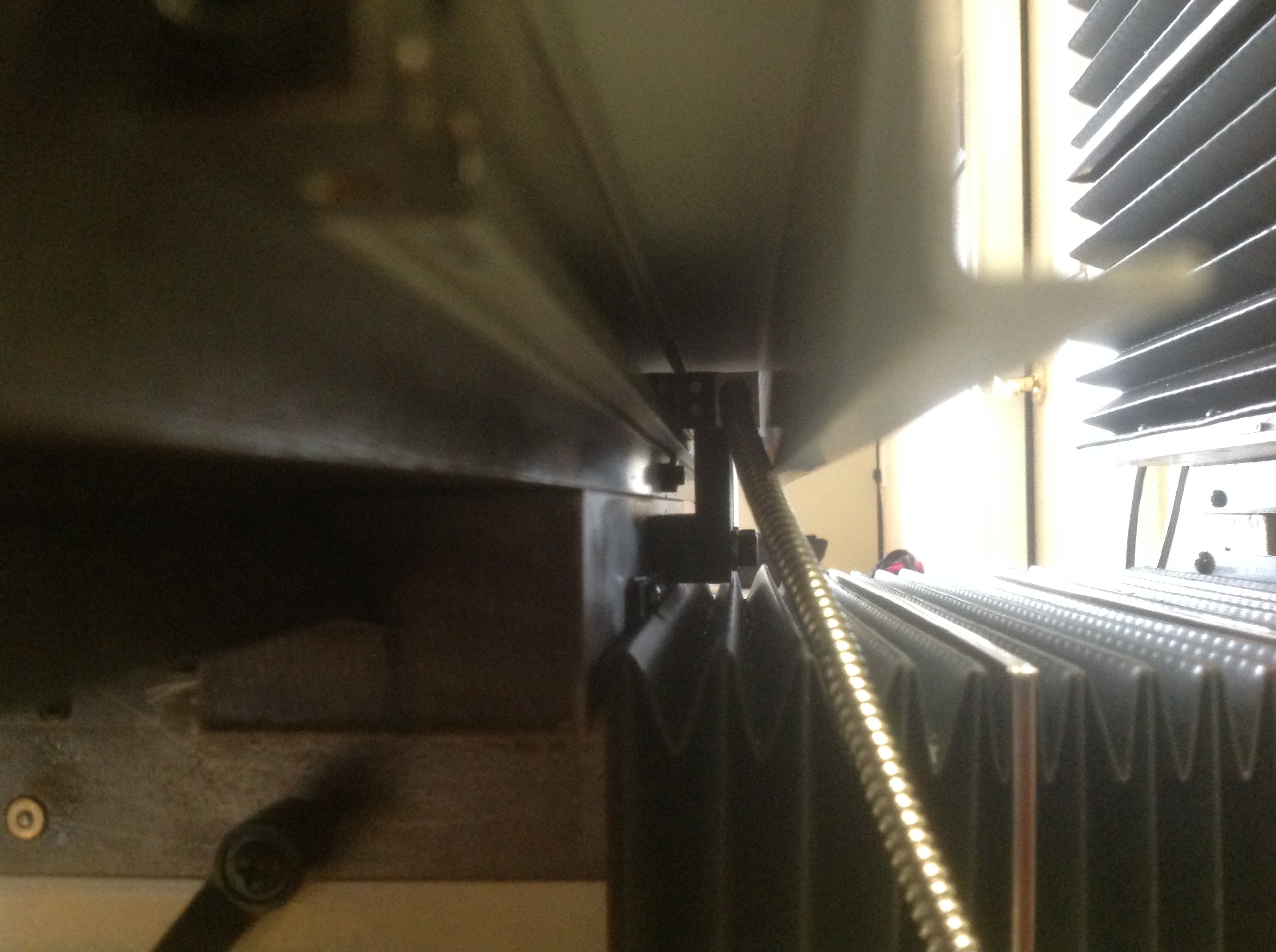
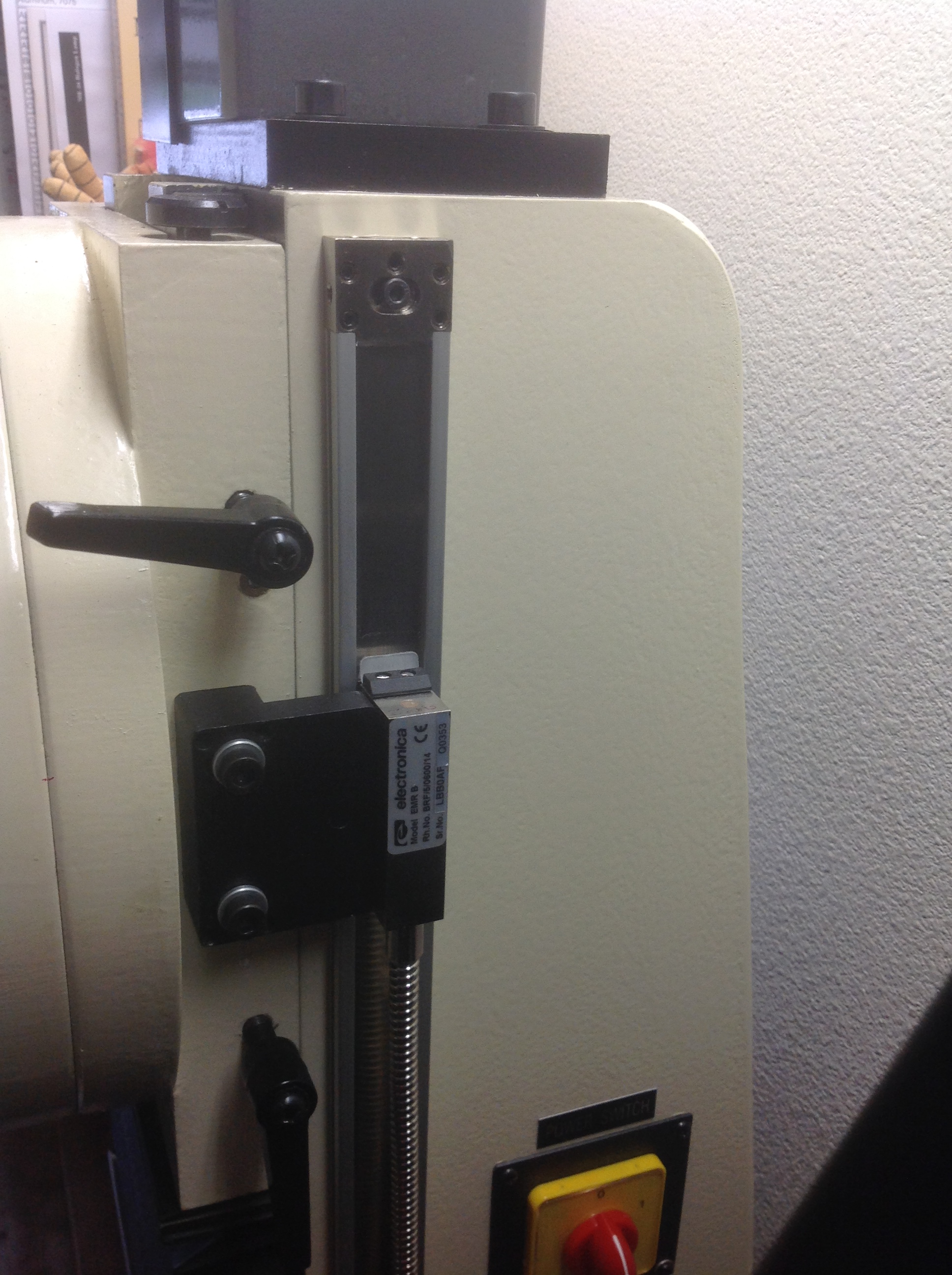
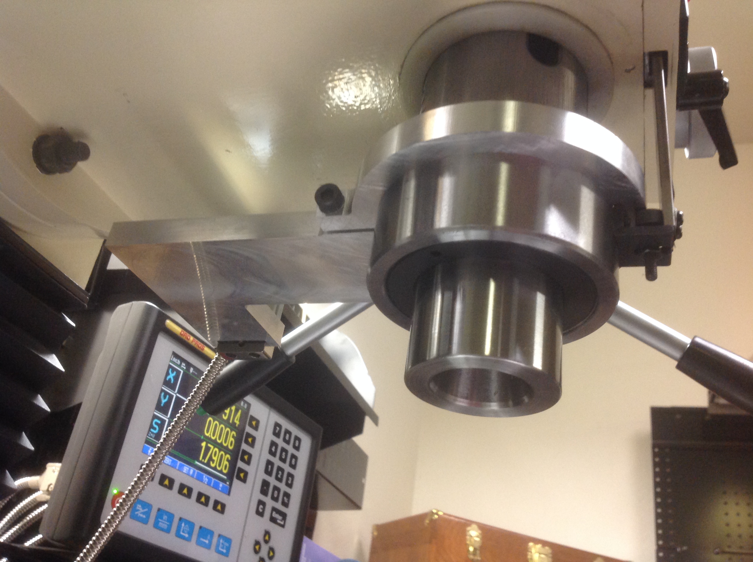
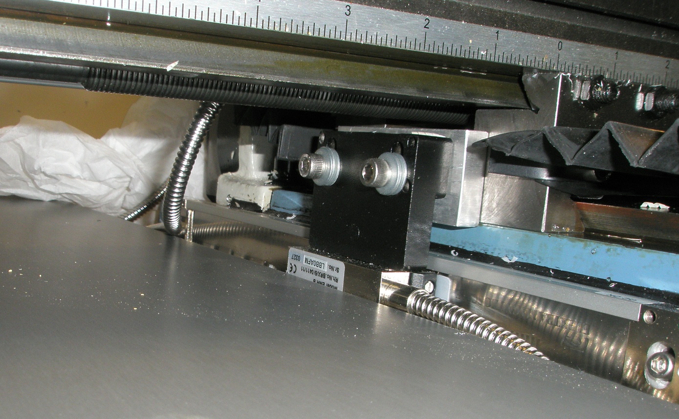
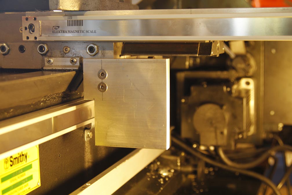
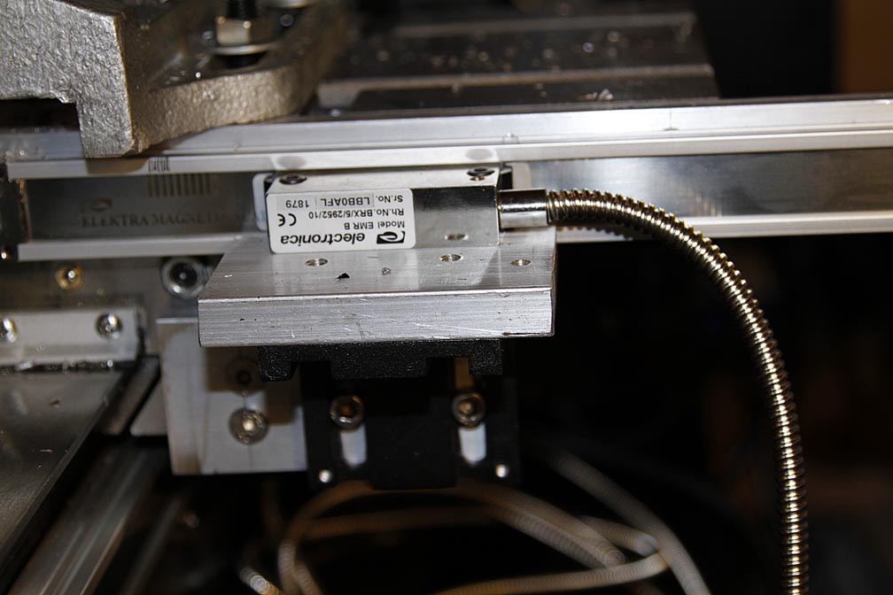
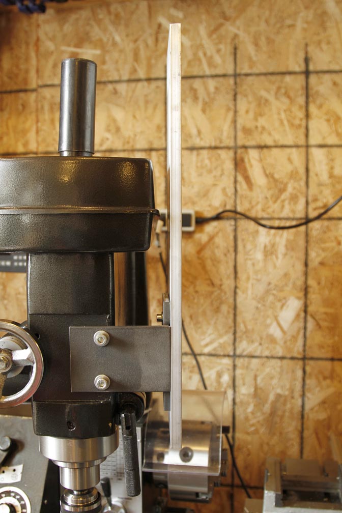
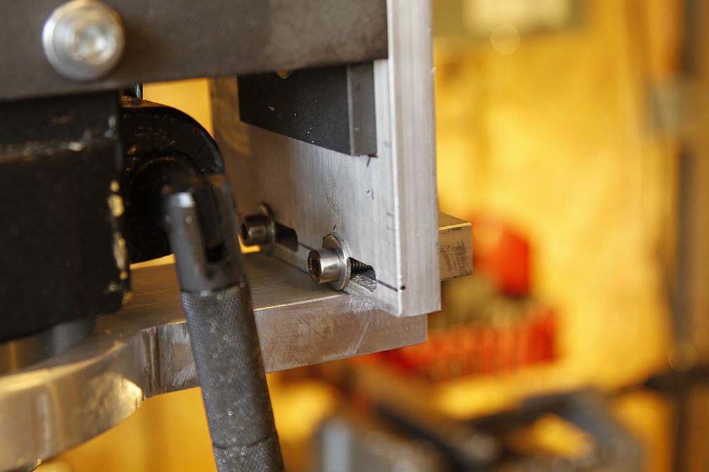
#7 - Courtesy
of "Skypilot" Genseal with a DRO PROS Electronica Magnetic Scale Mill
Kit:

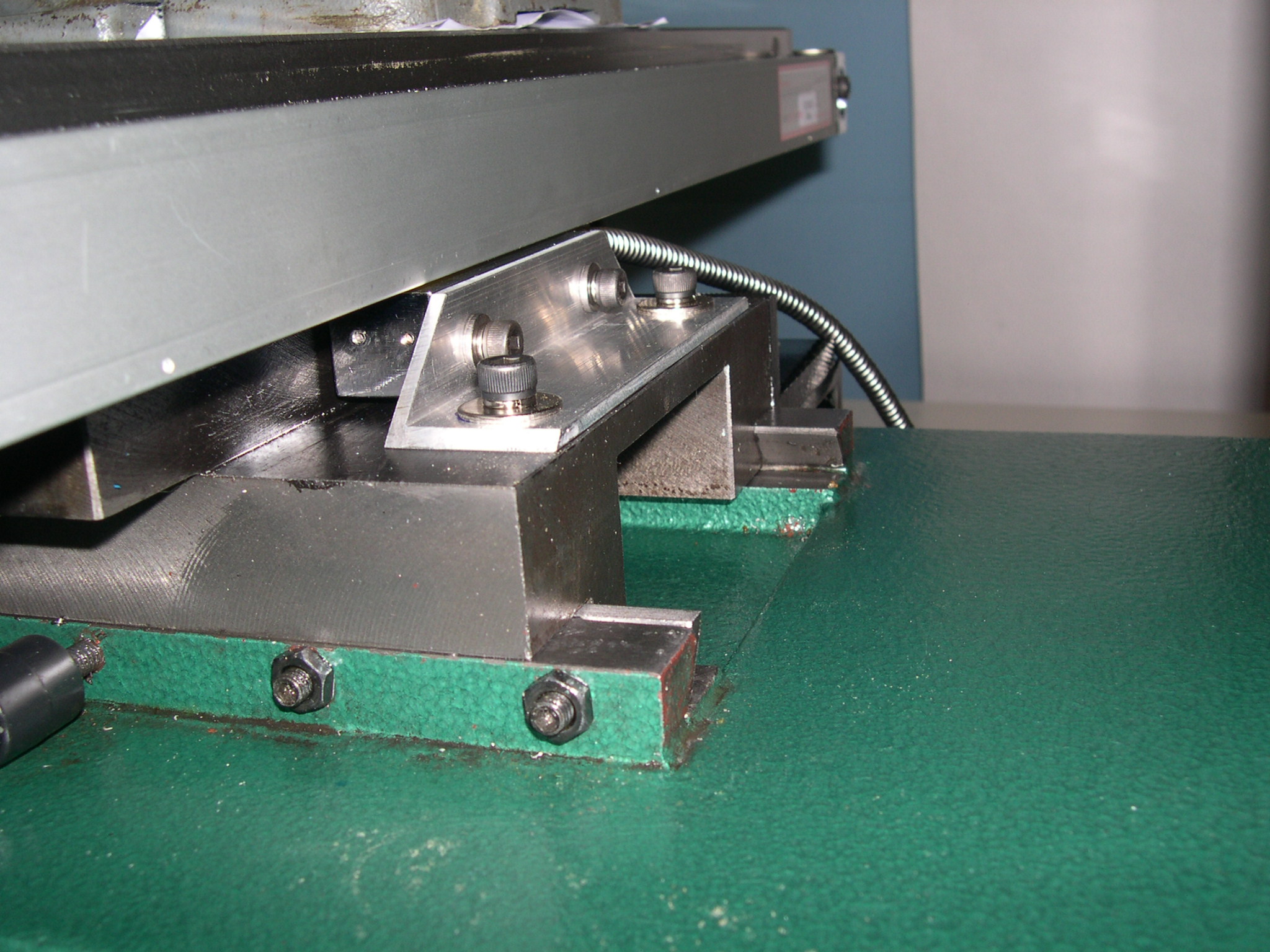
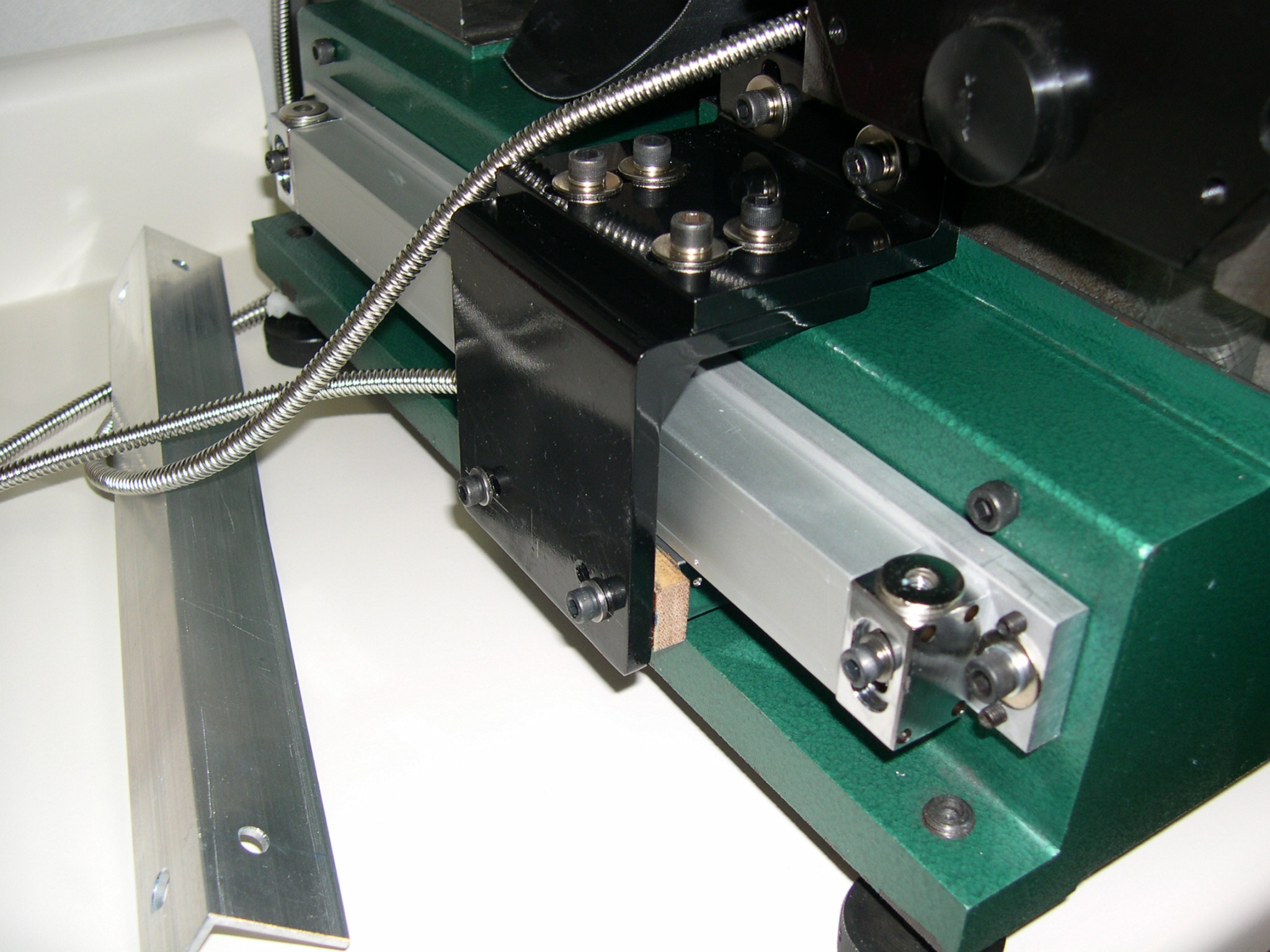
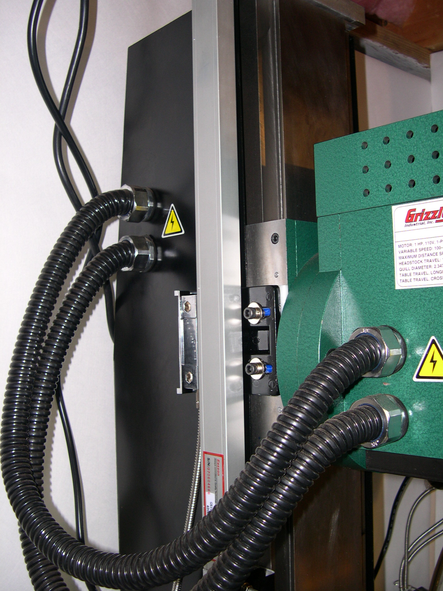
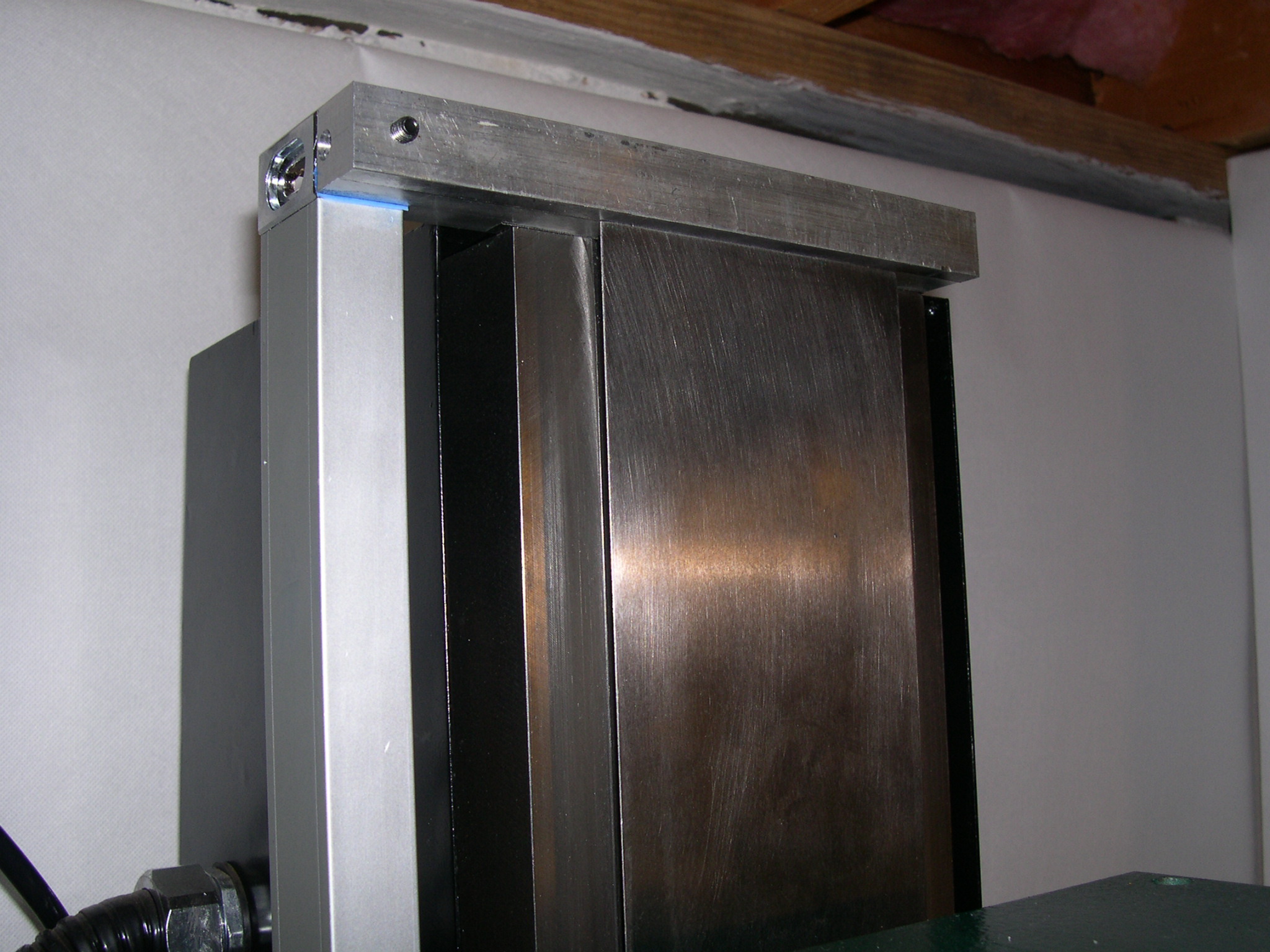
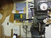
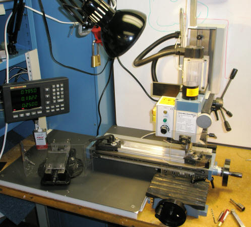
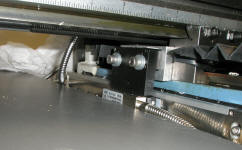
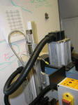
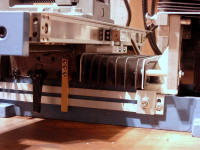
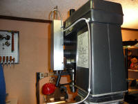
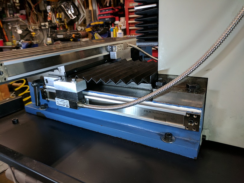
#8 - Courtesy
of D. Serles with an EL400 2 axis Lathe Kit:
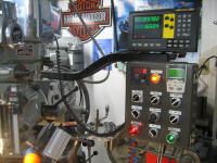
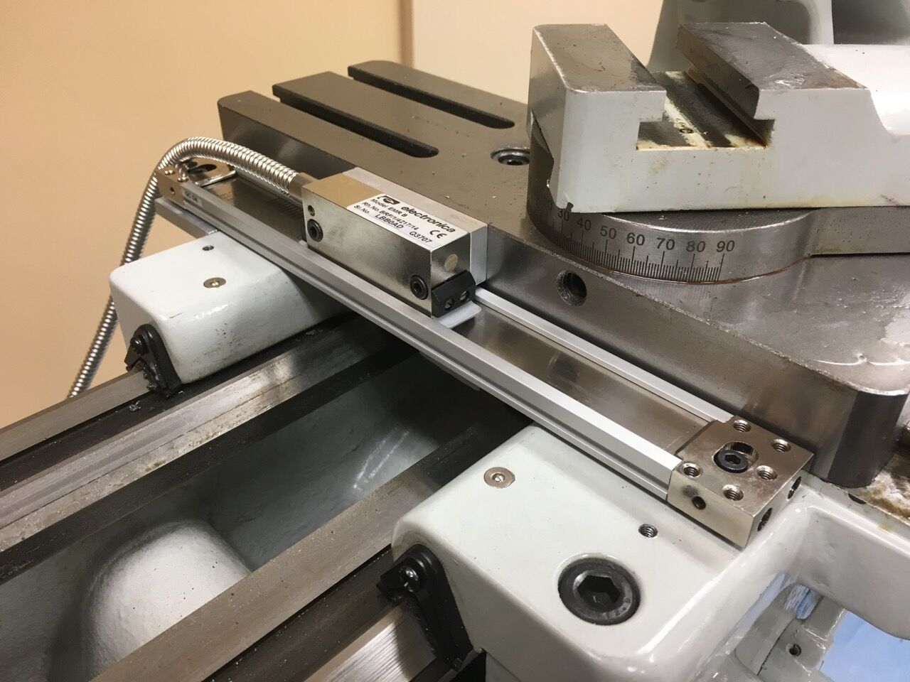
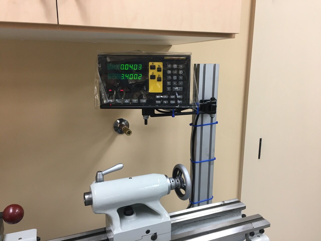
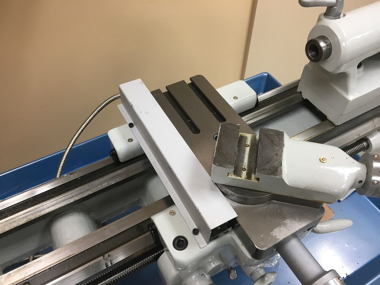
#9 - Courtesy
of Eric with an EL700 4 axis Magnetic Scale Kit:
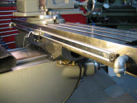
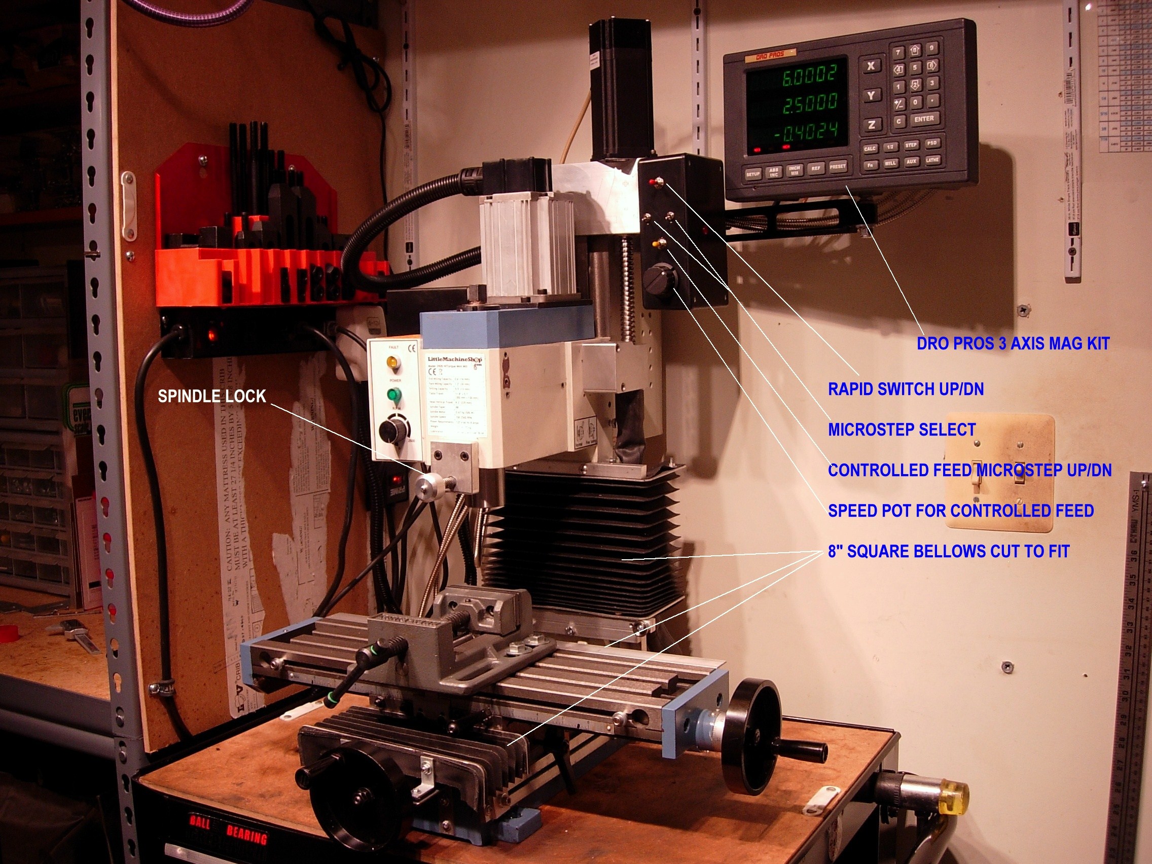
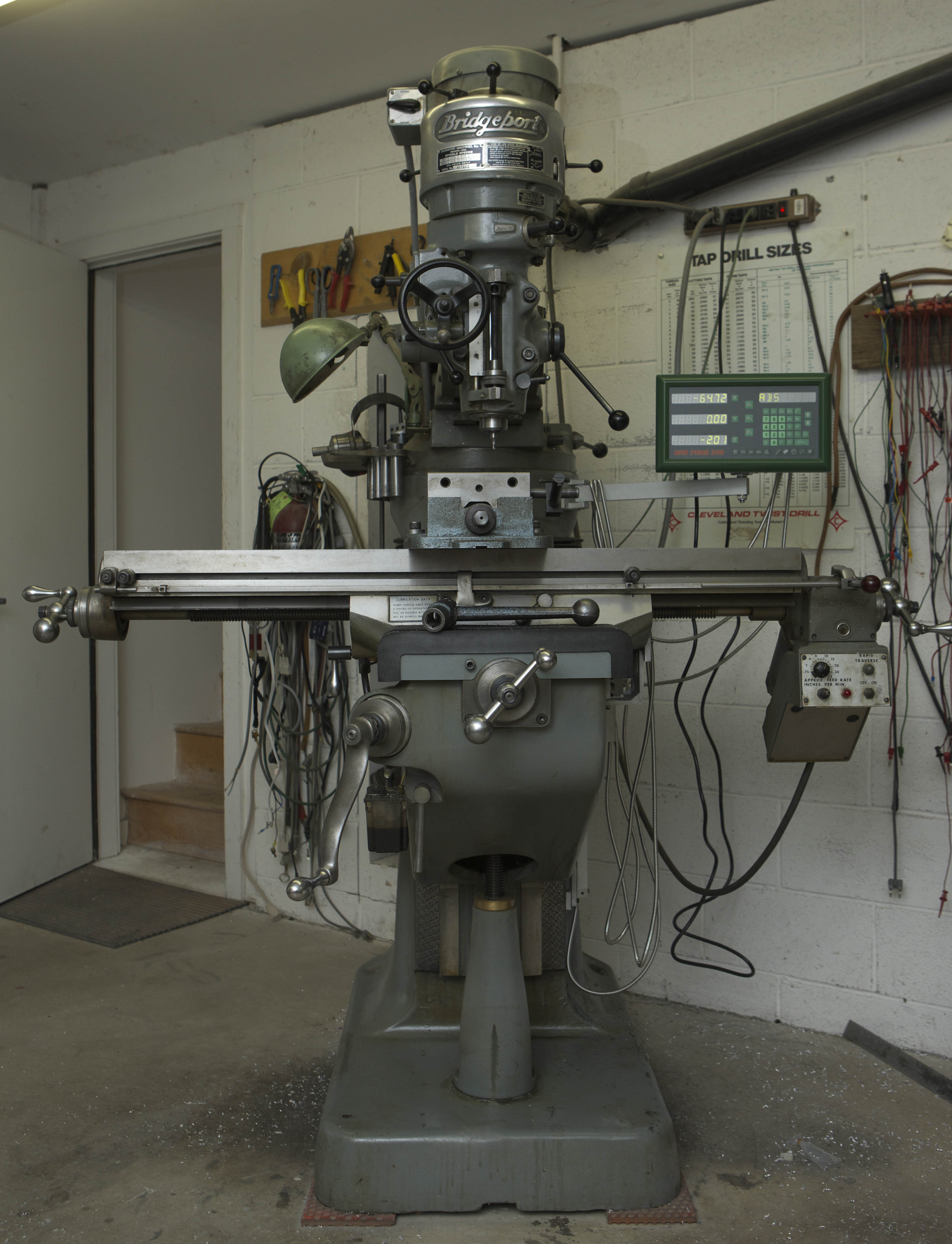
#10 - Courtesy
of G. Whitman with a DRO PROS Electronica Magnetic Scale Mill Kit:
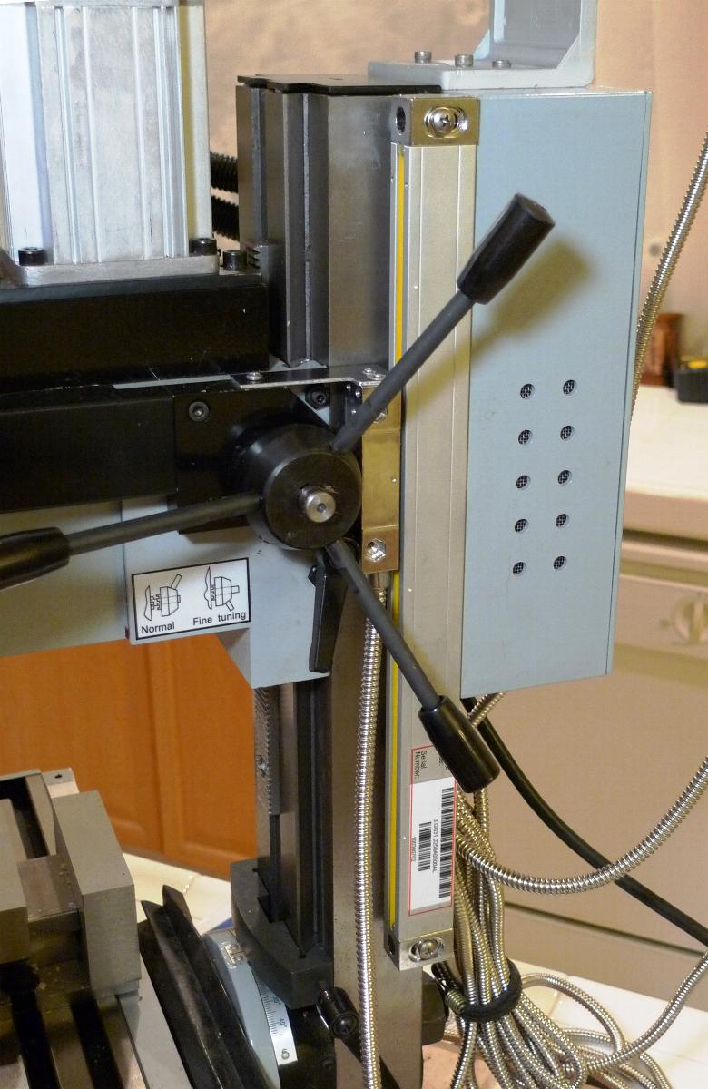
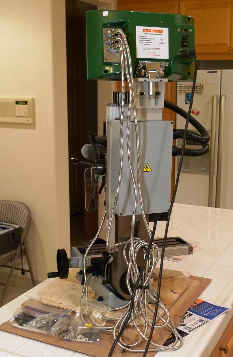
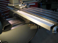
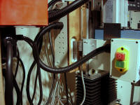
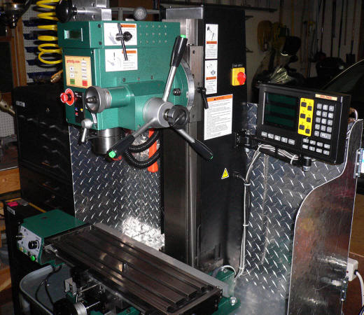
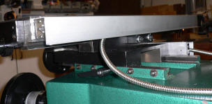
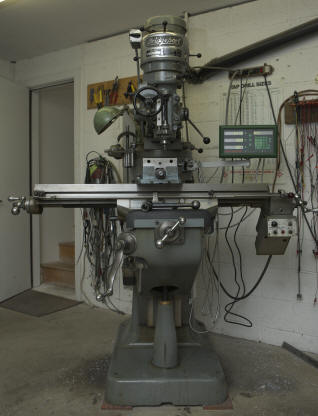
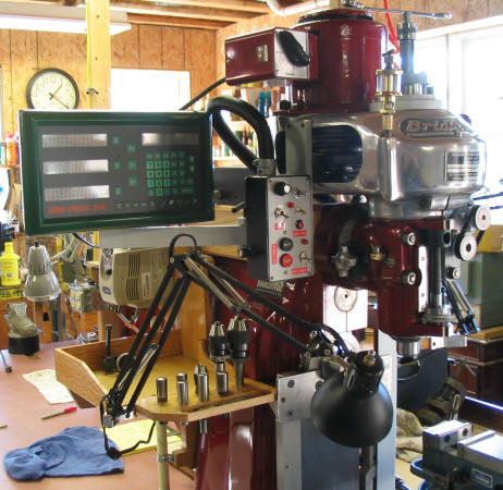
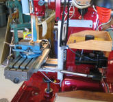
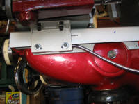
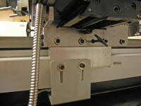
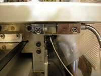
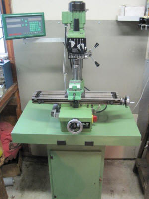
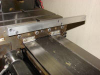
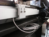
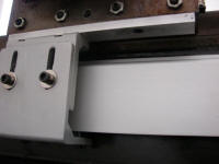
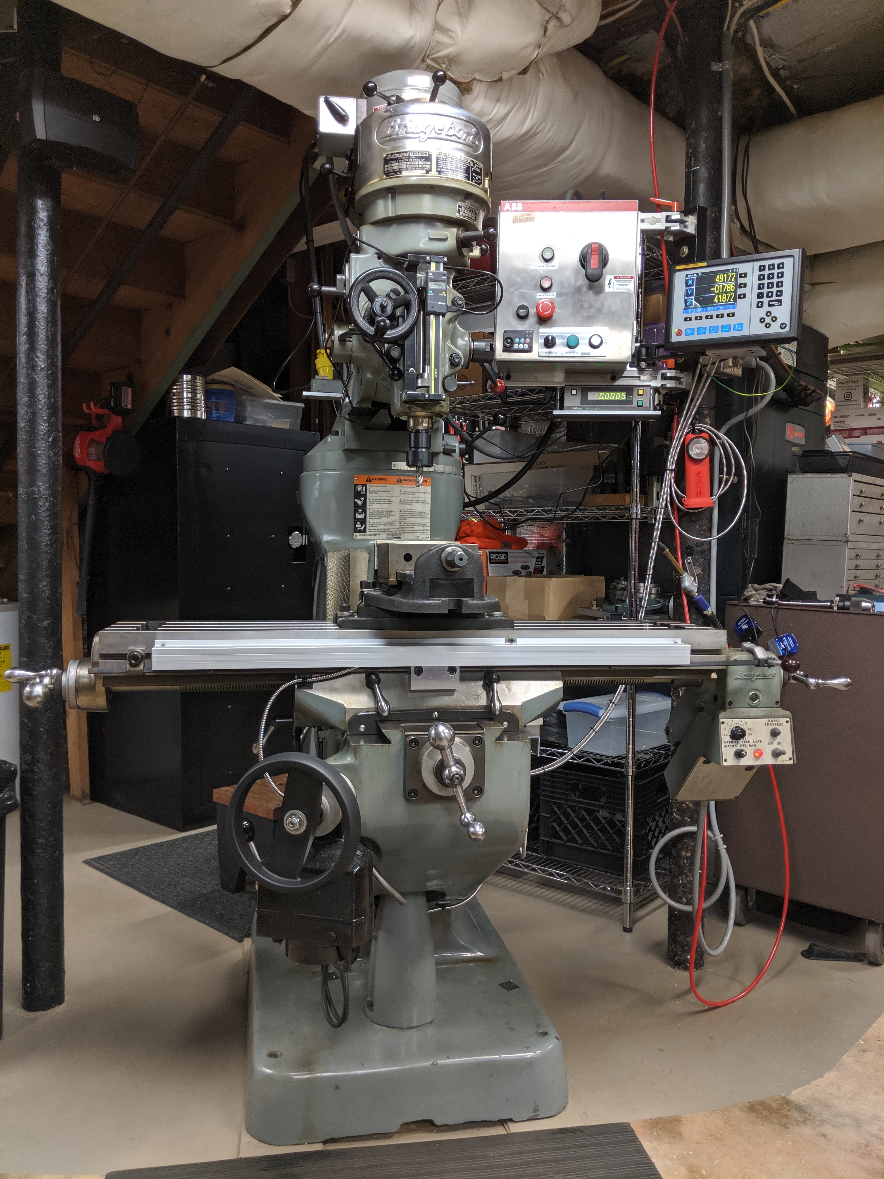
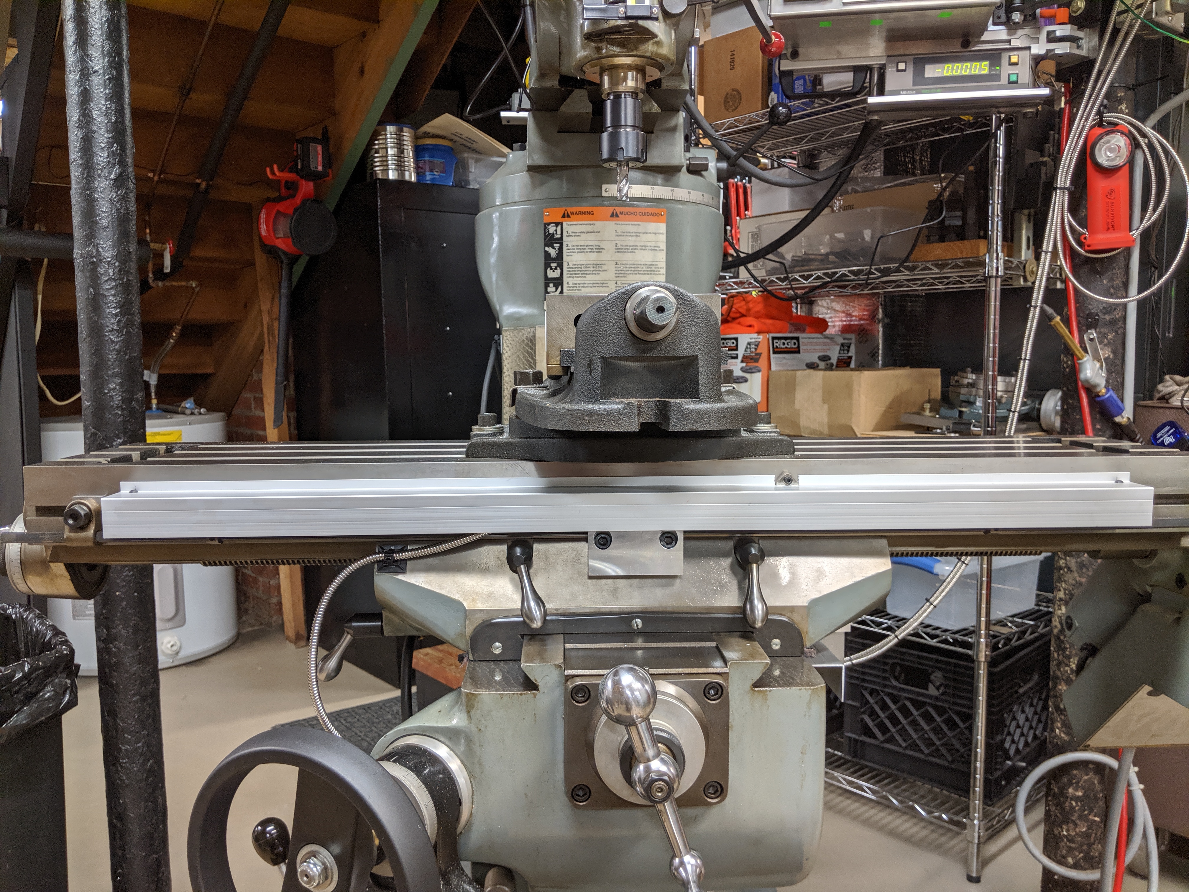
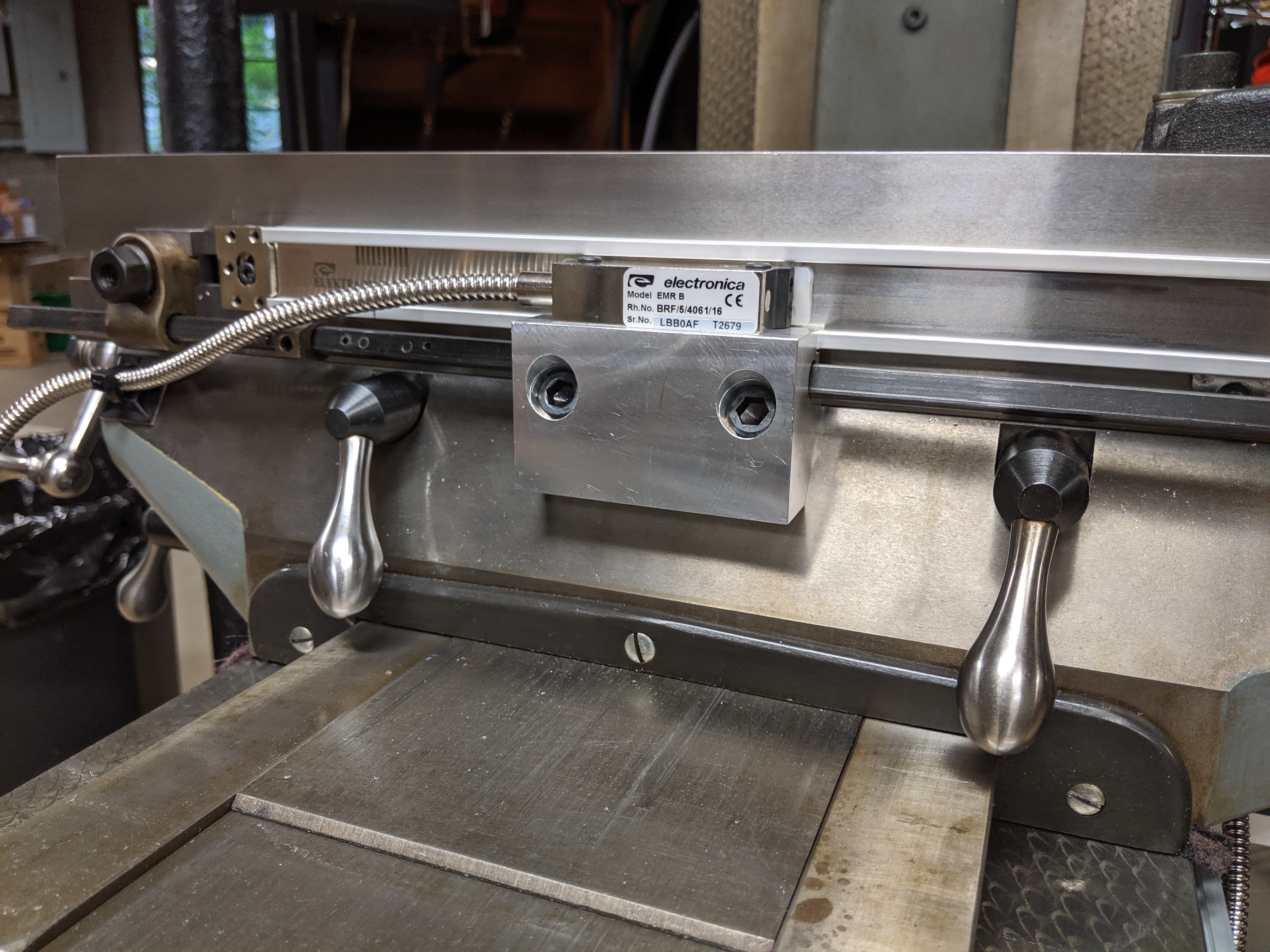
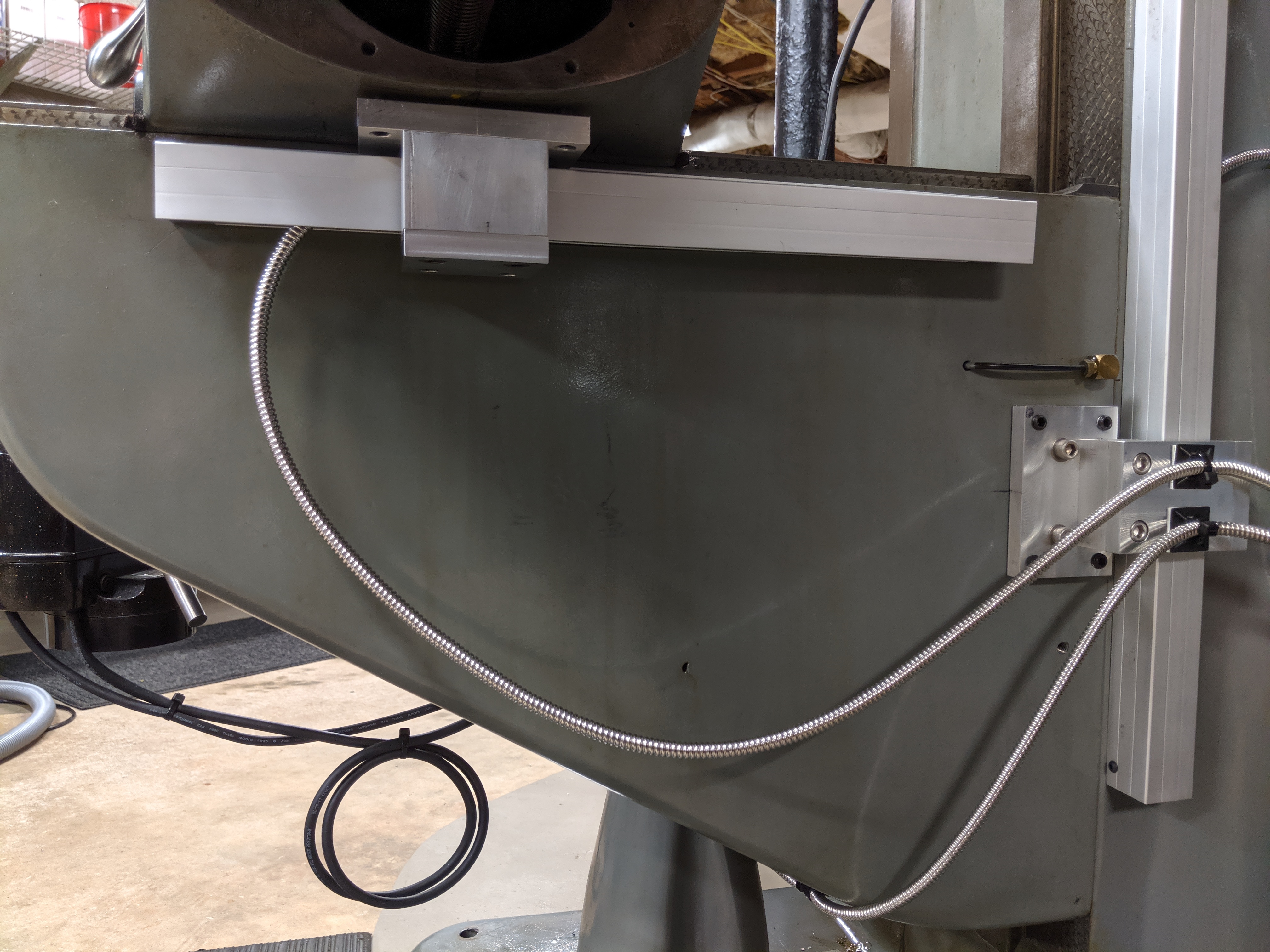
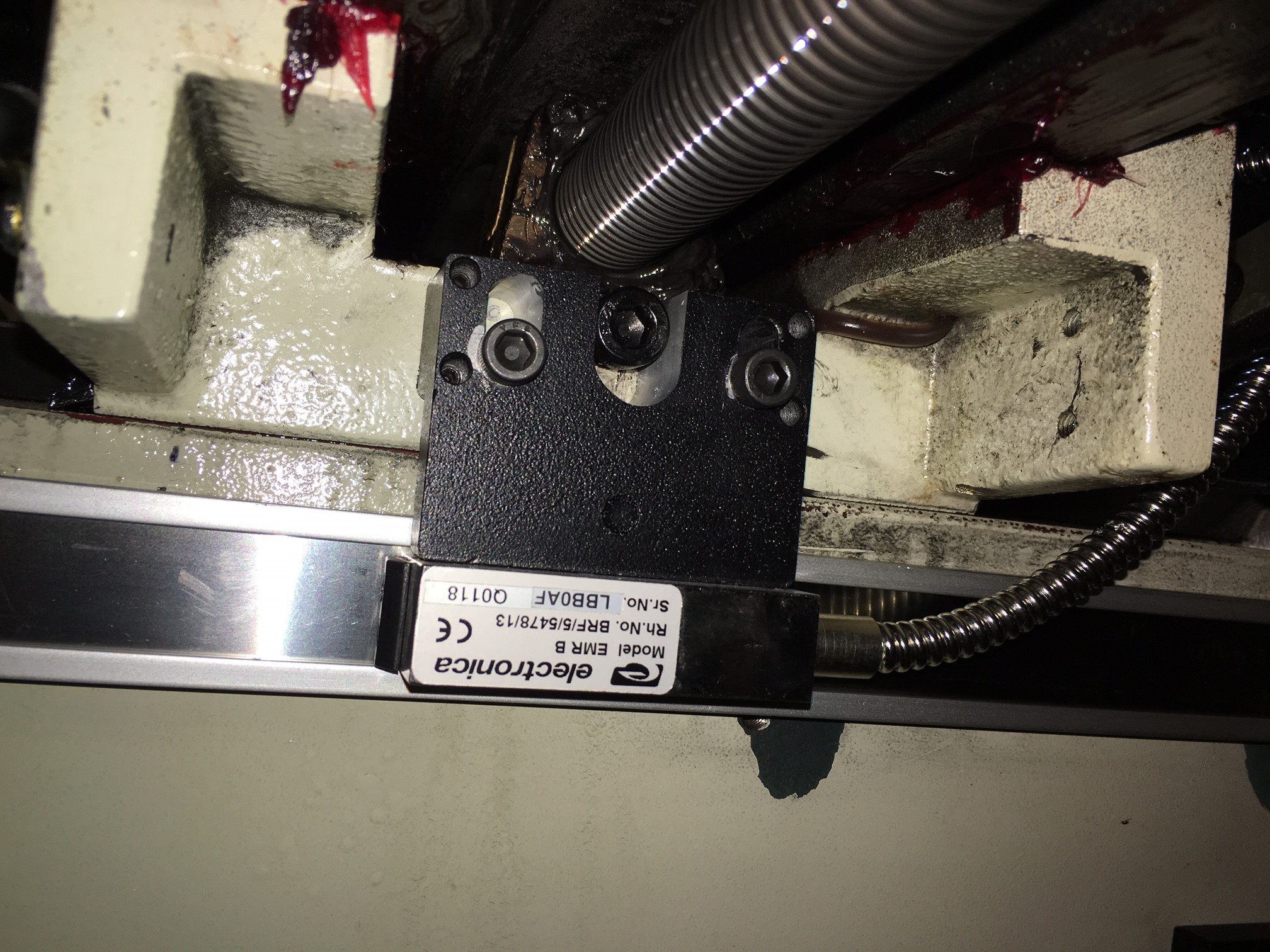
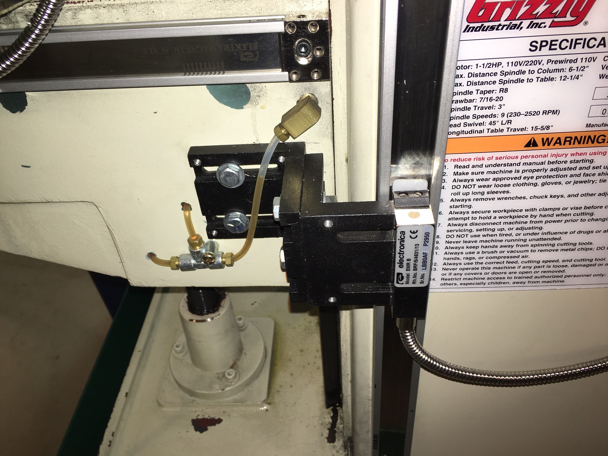
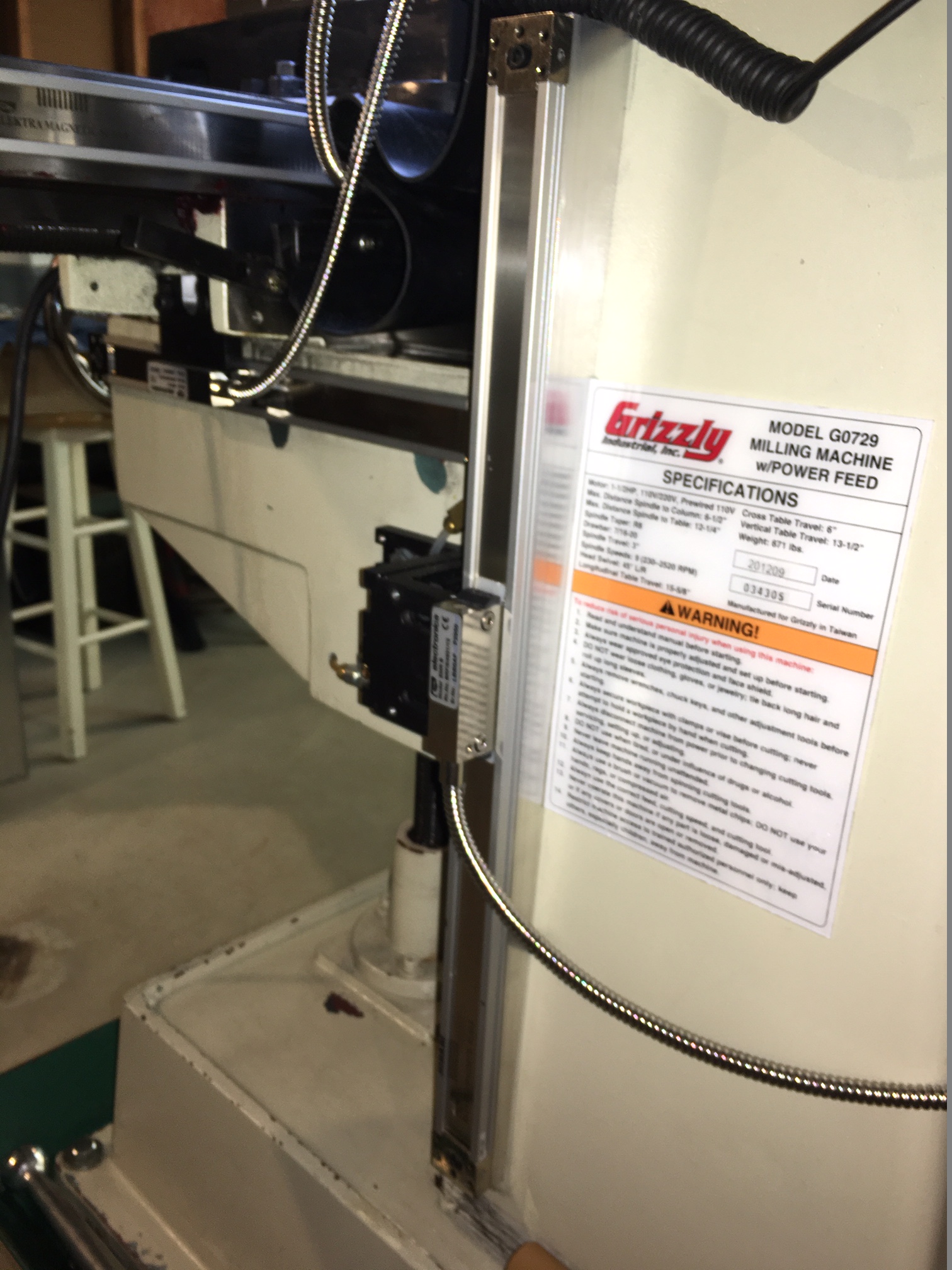
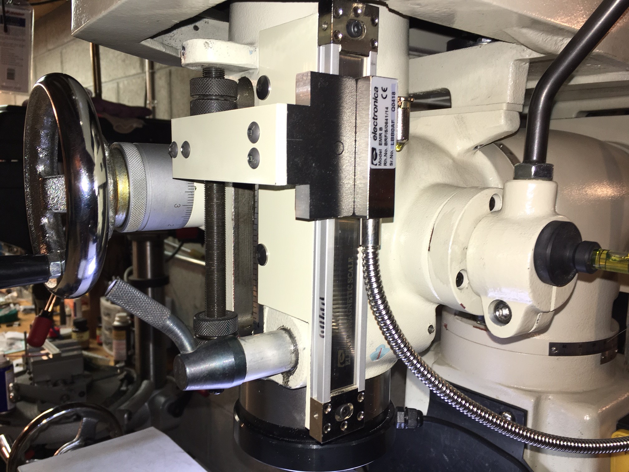
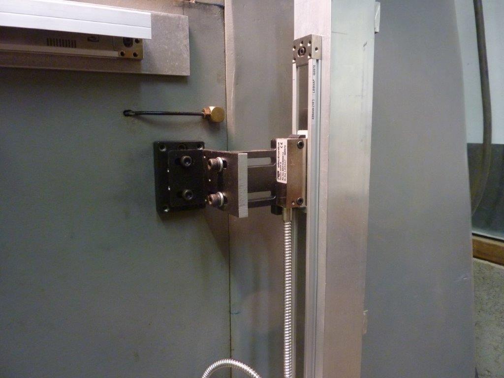
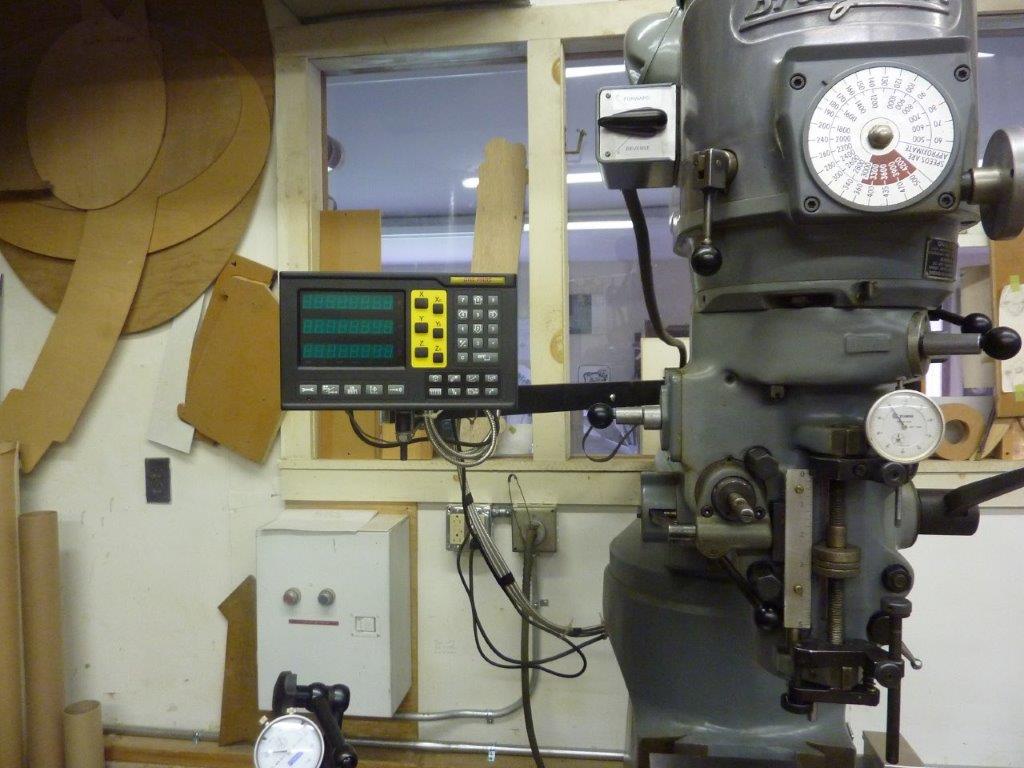
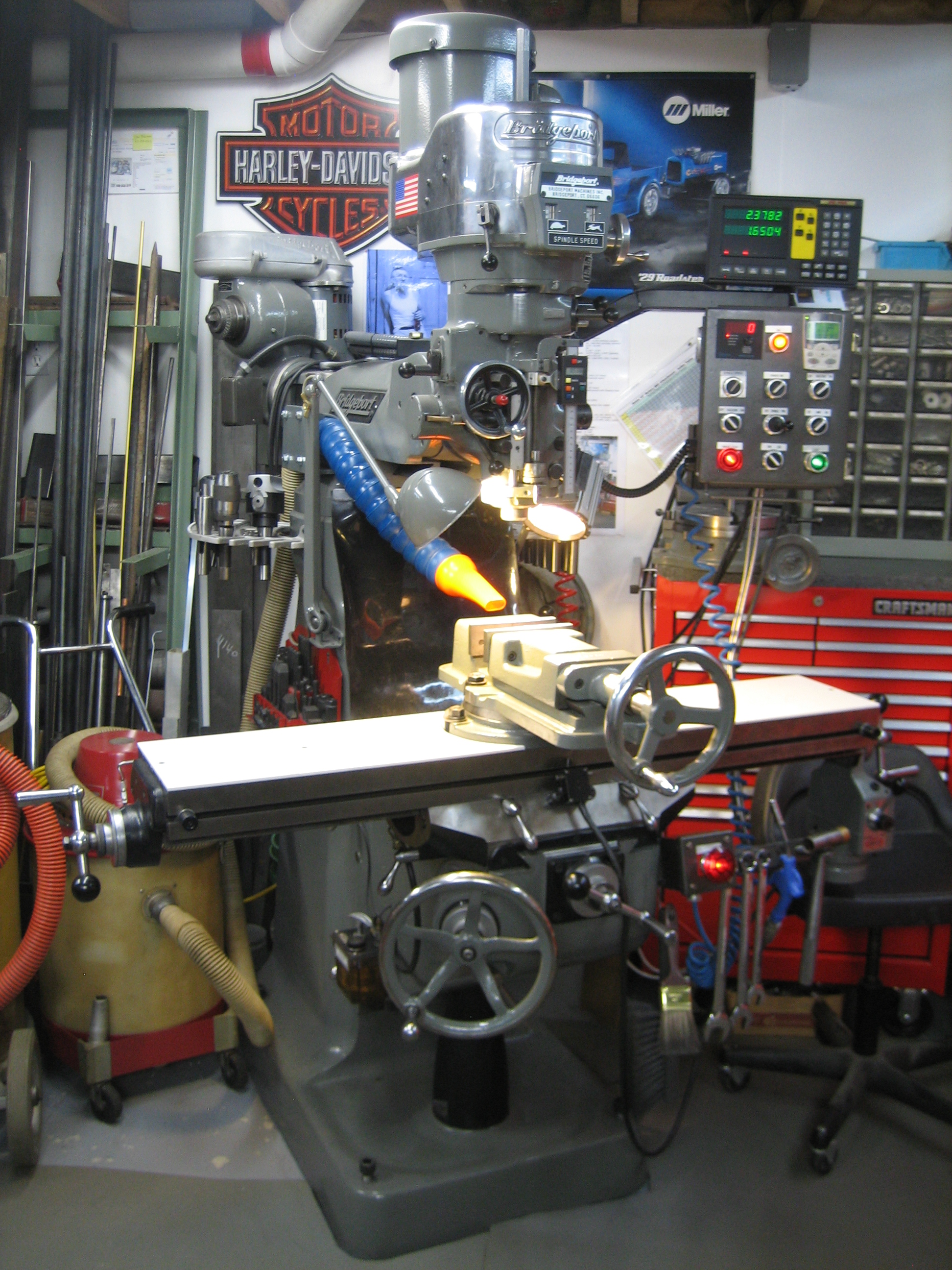
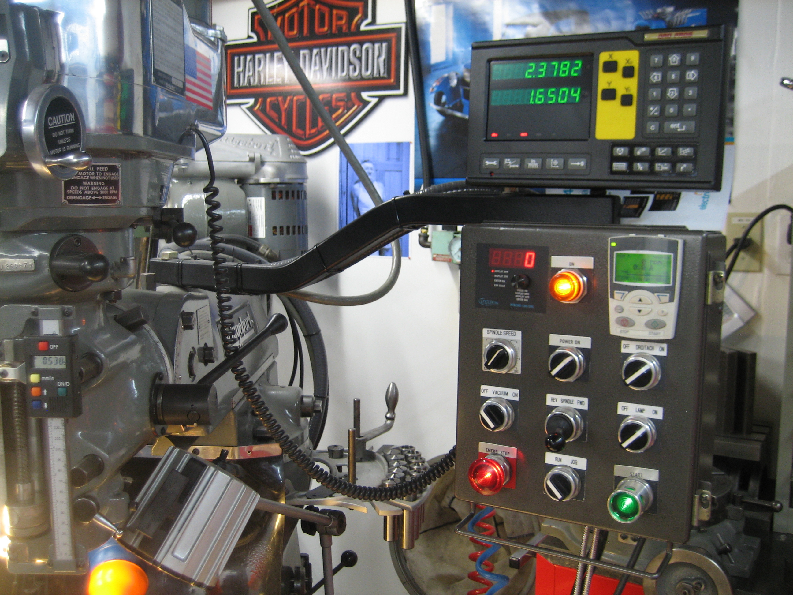
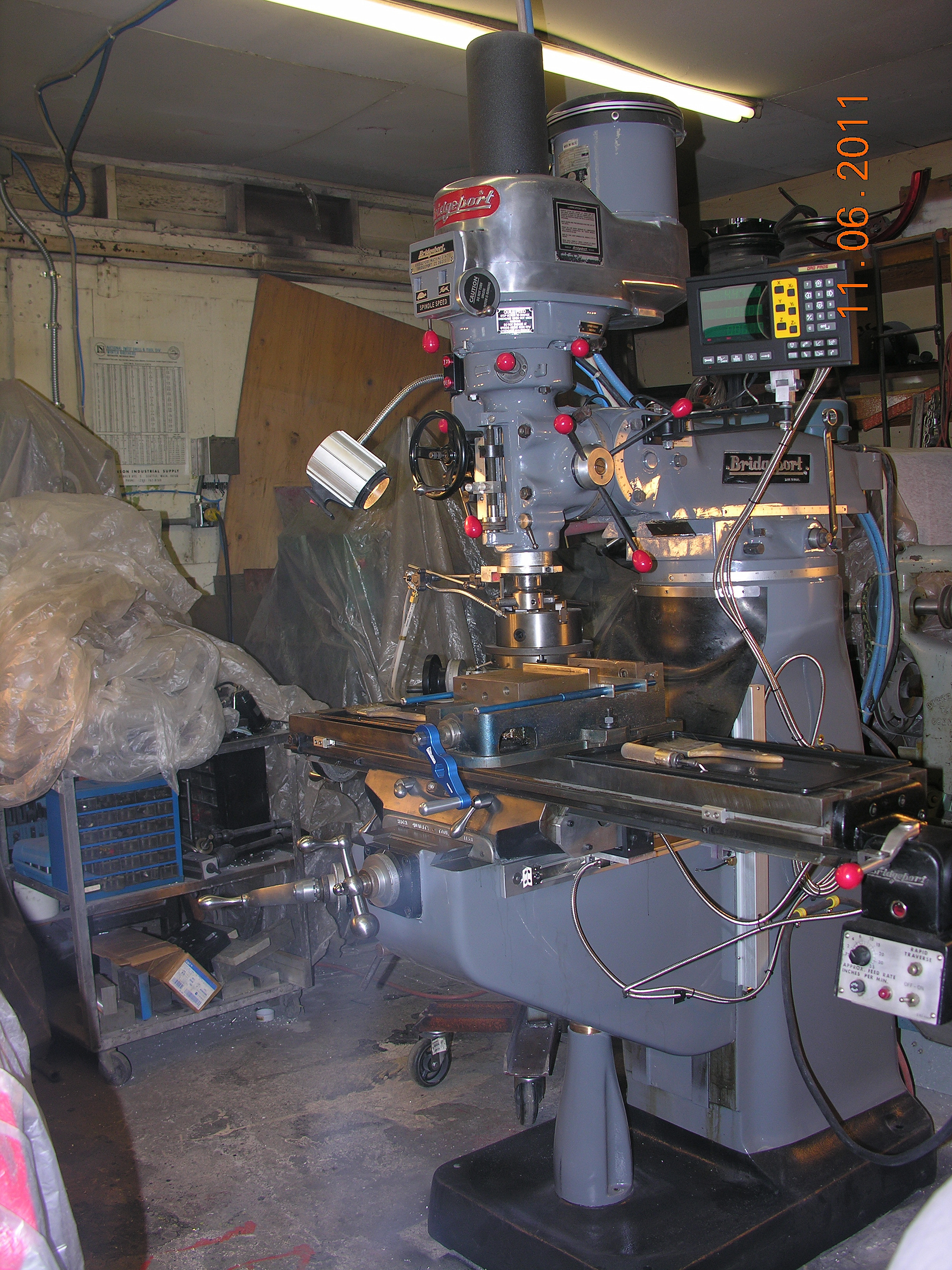
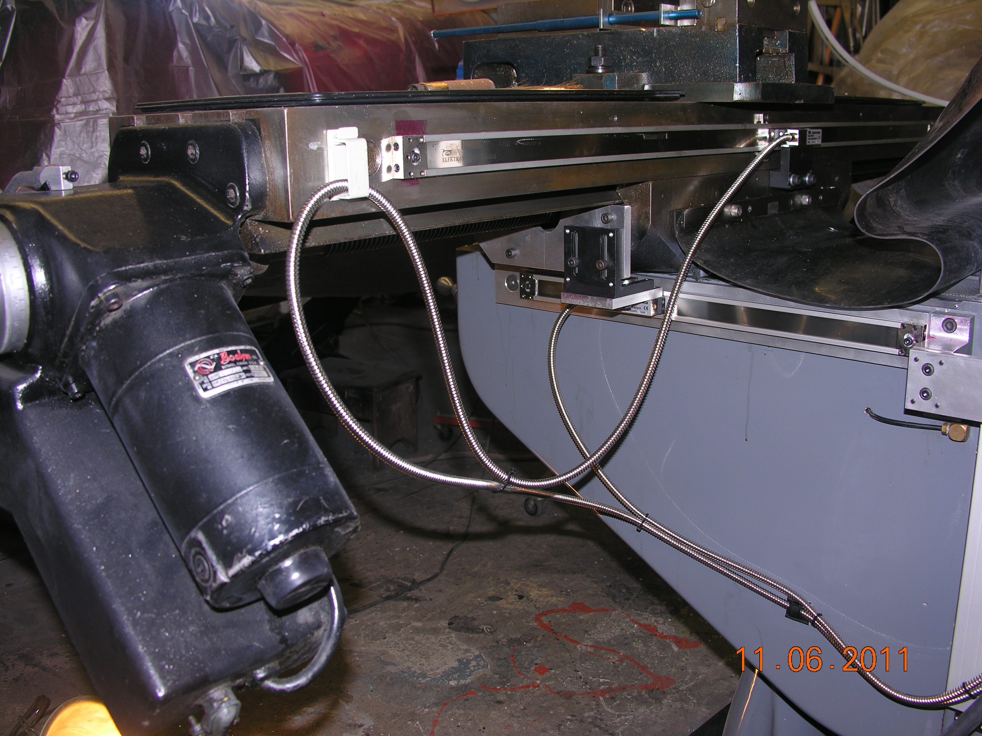
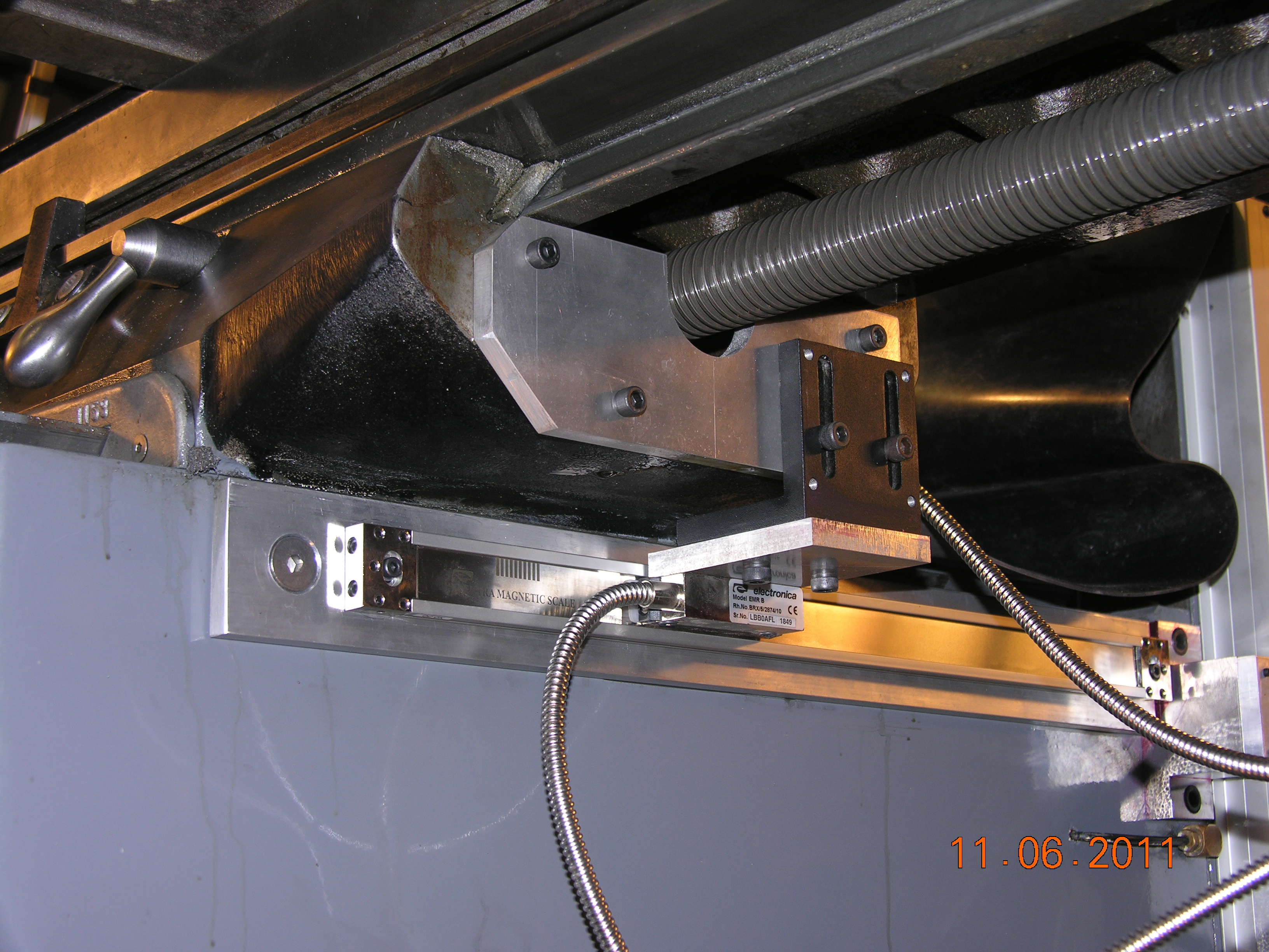
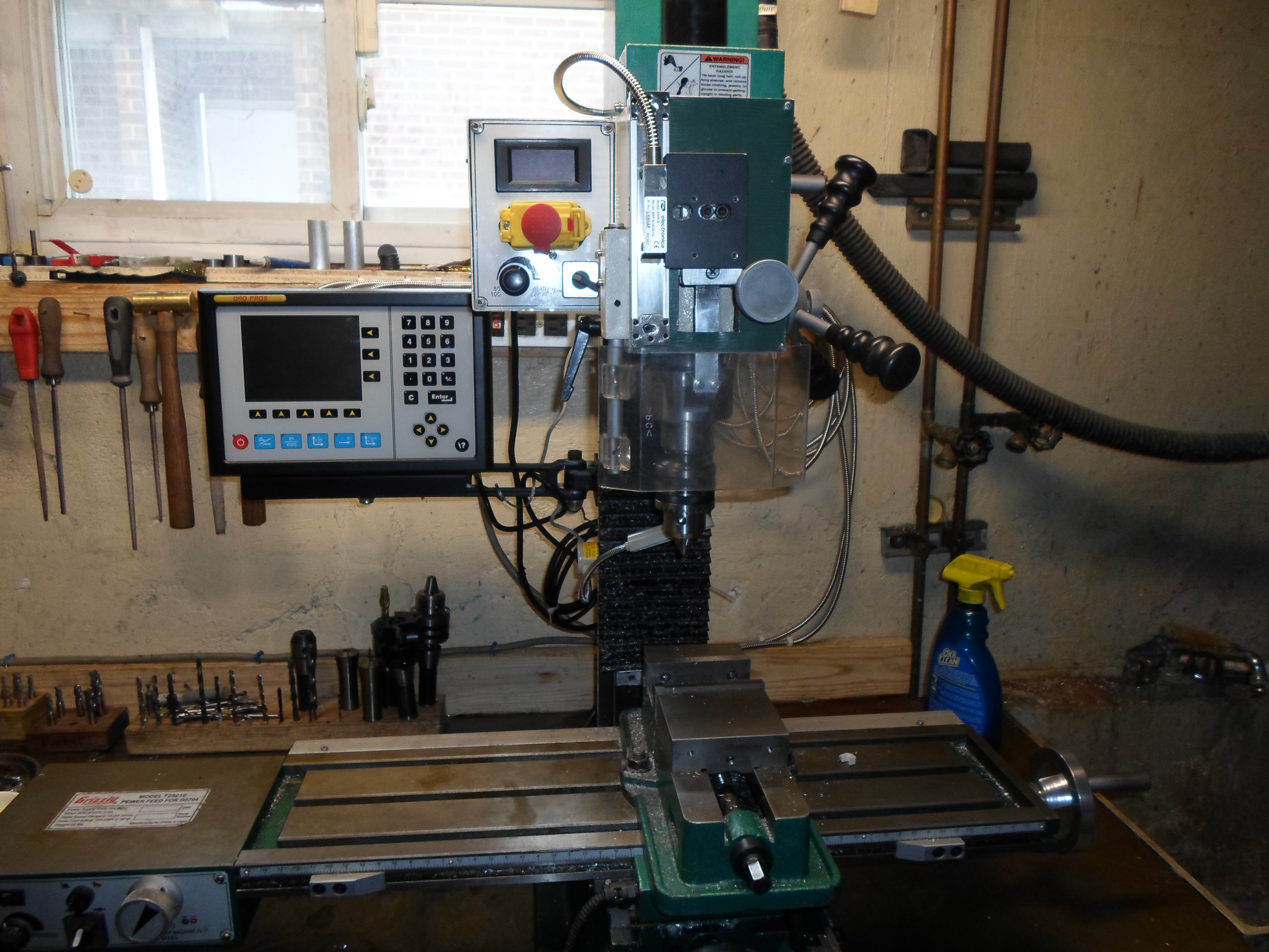
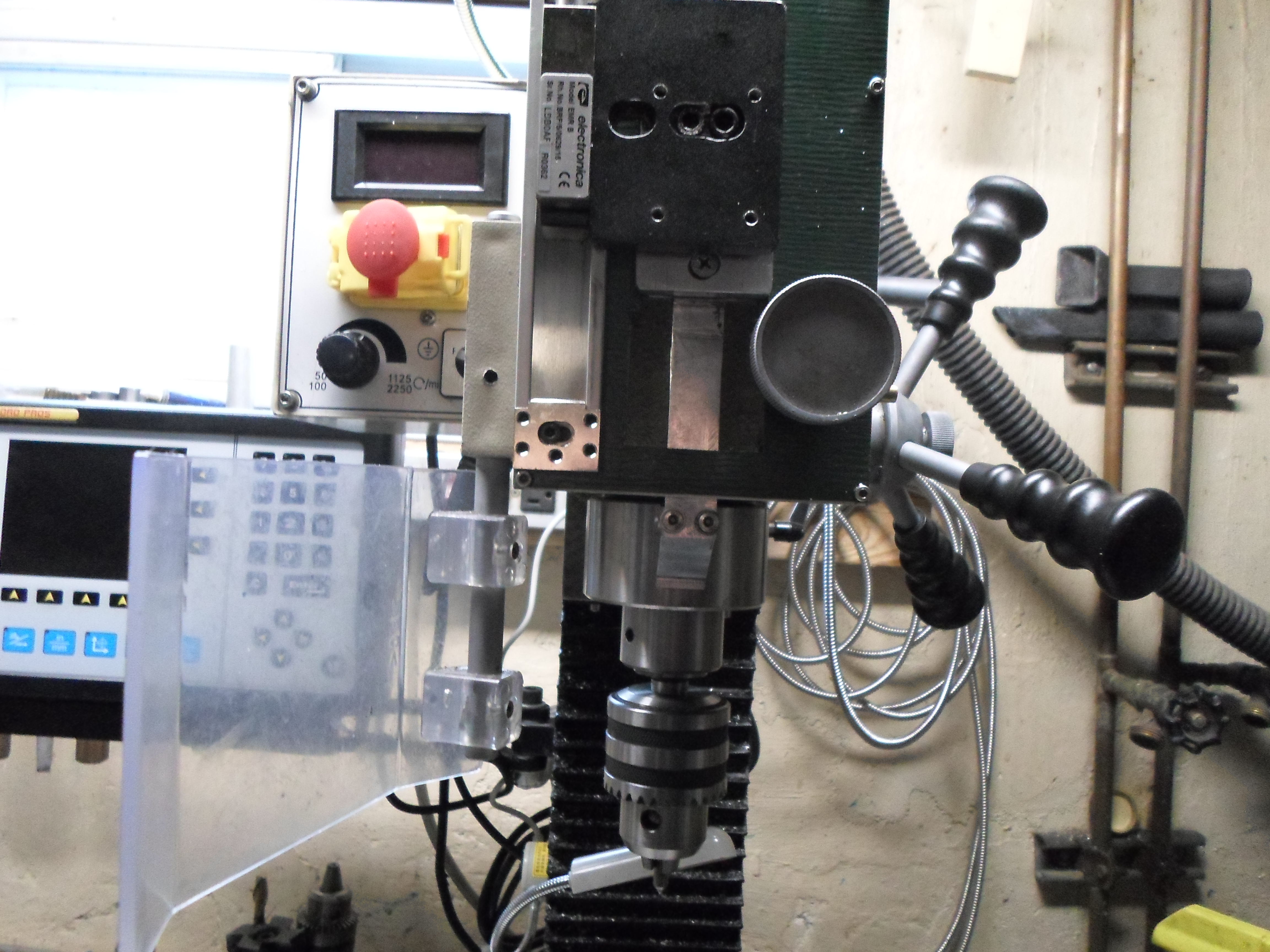
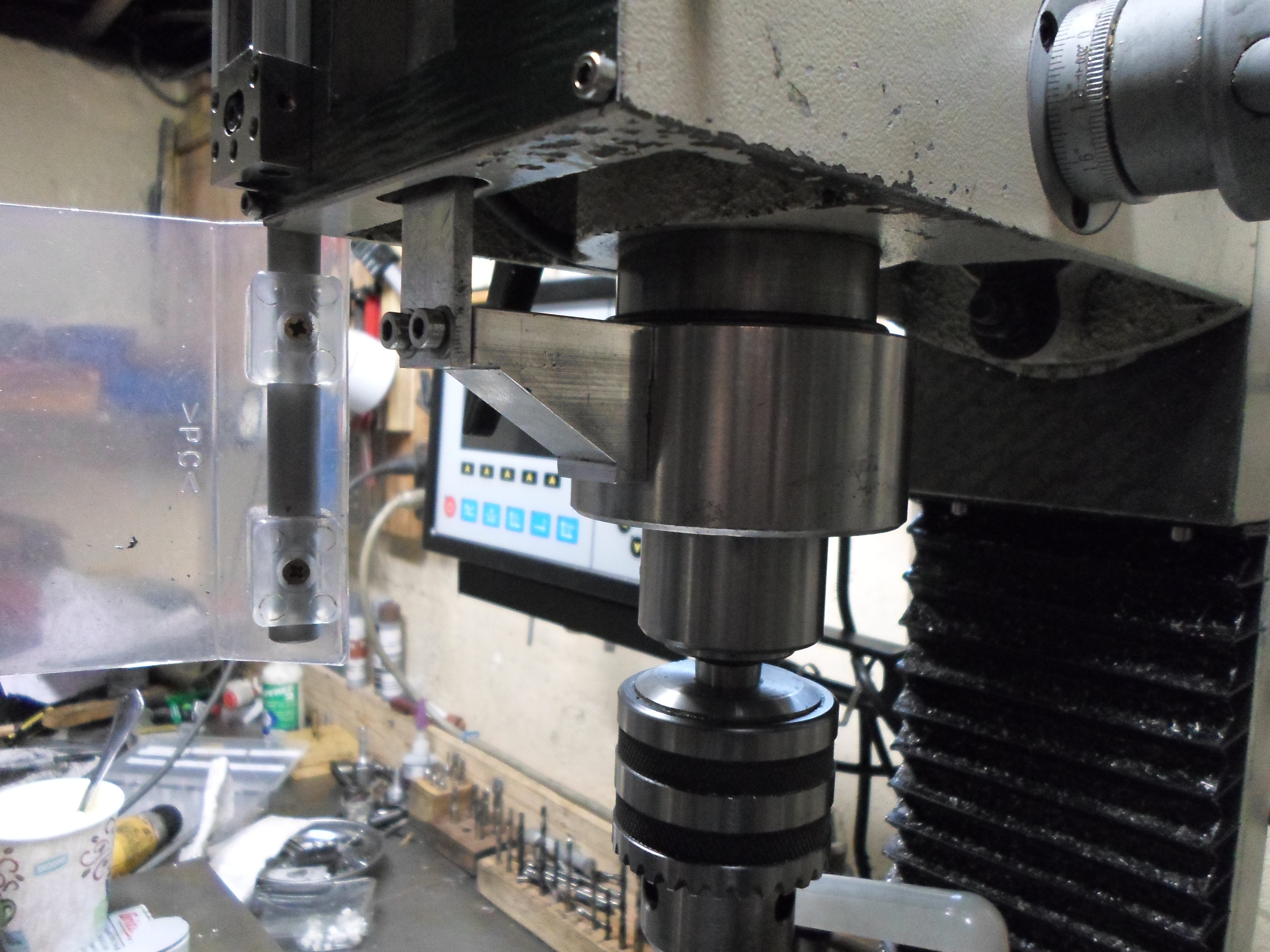
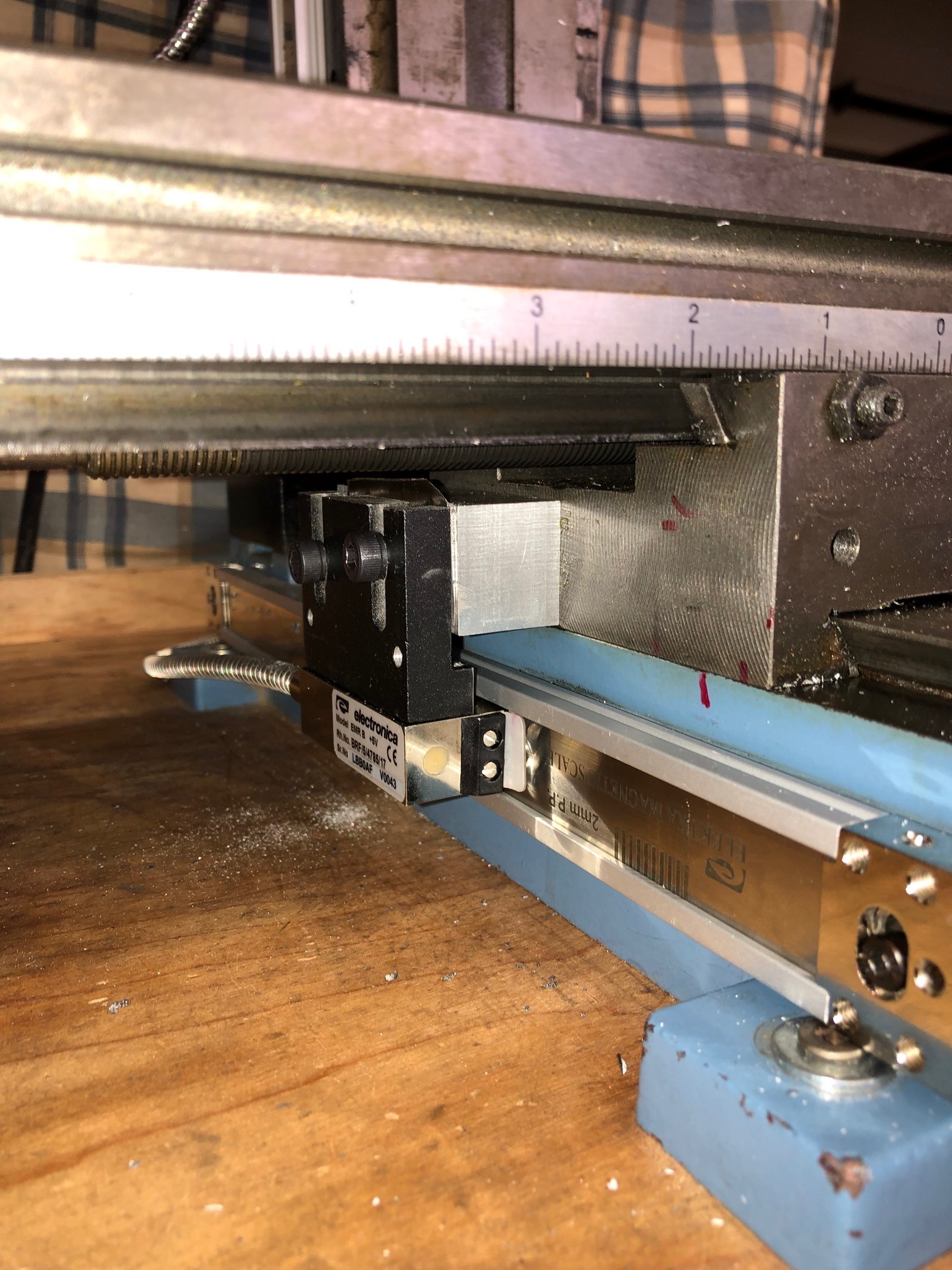
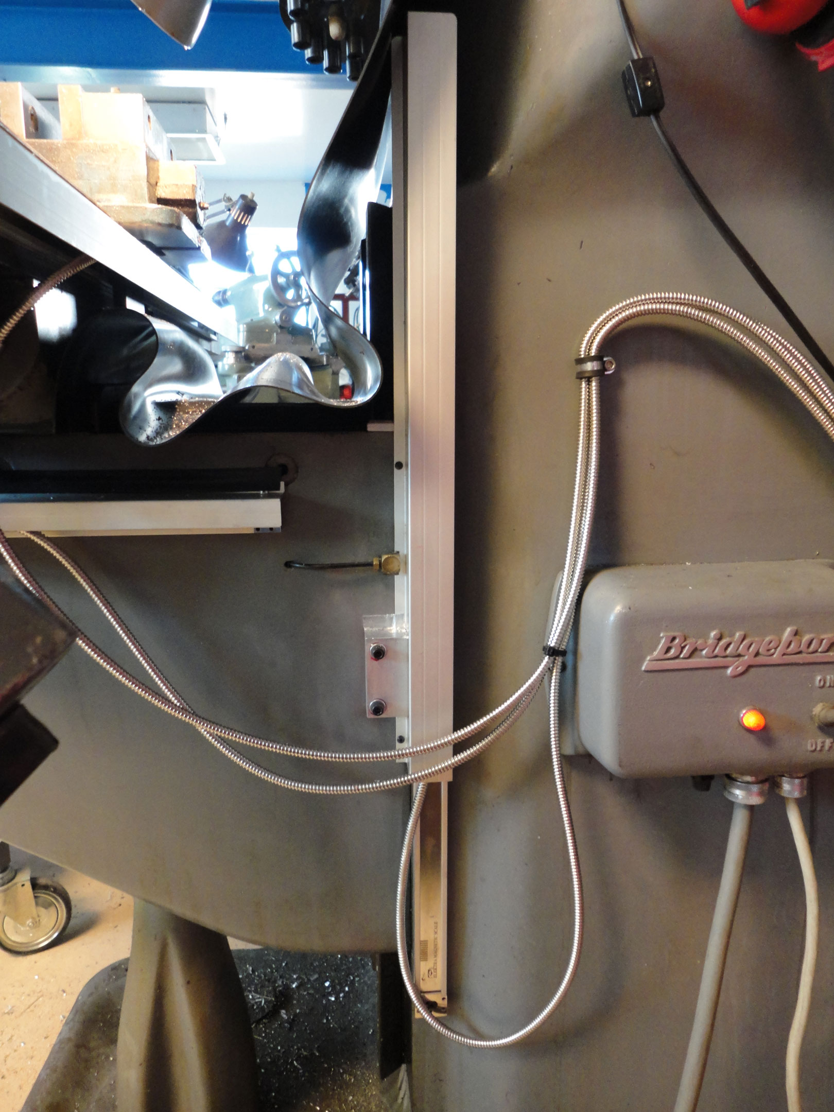
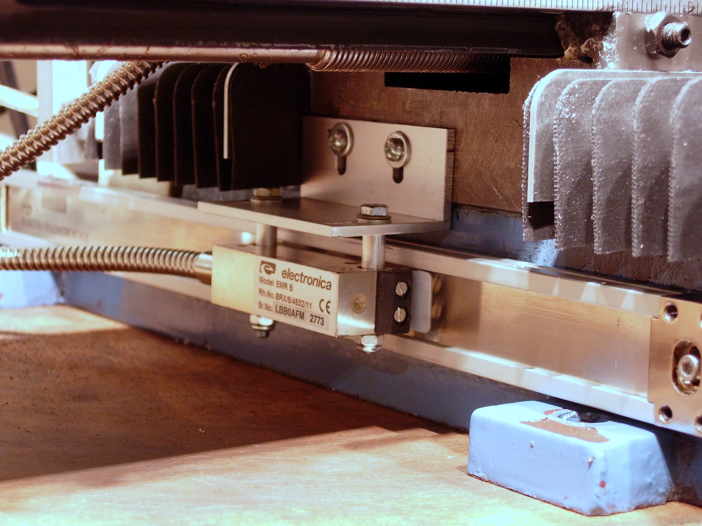
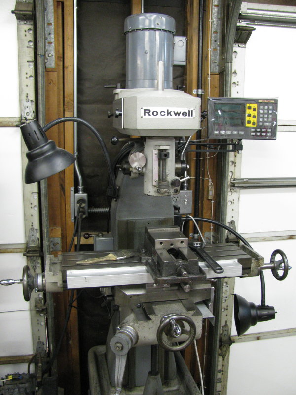
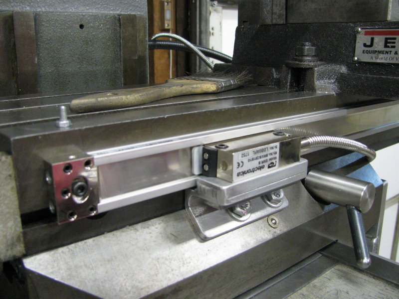
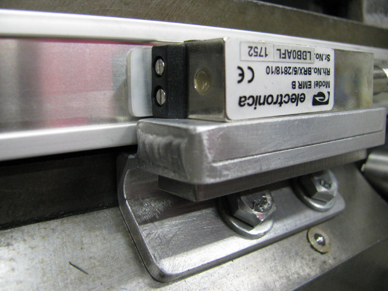
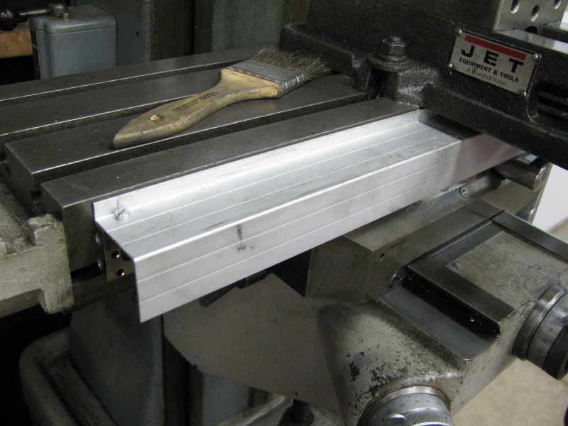
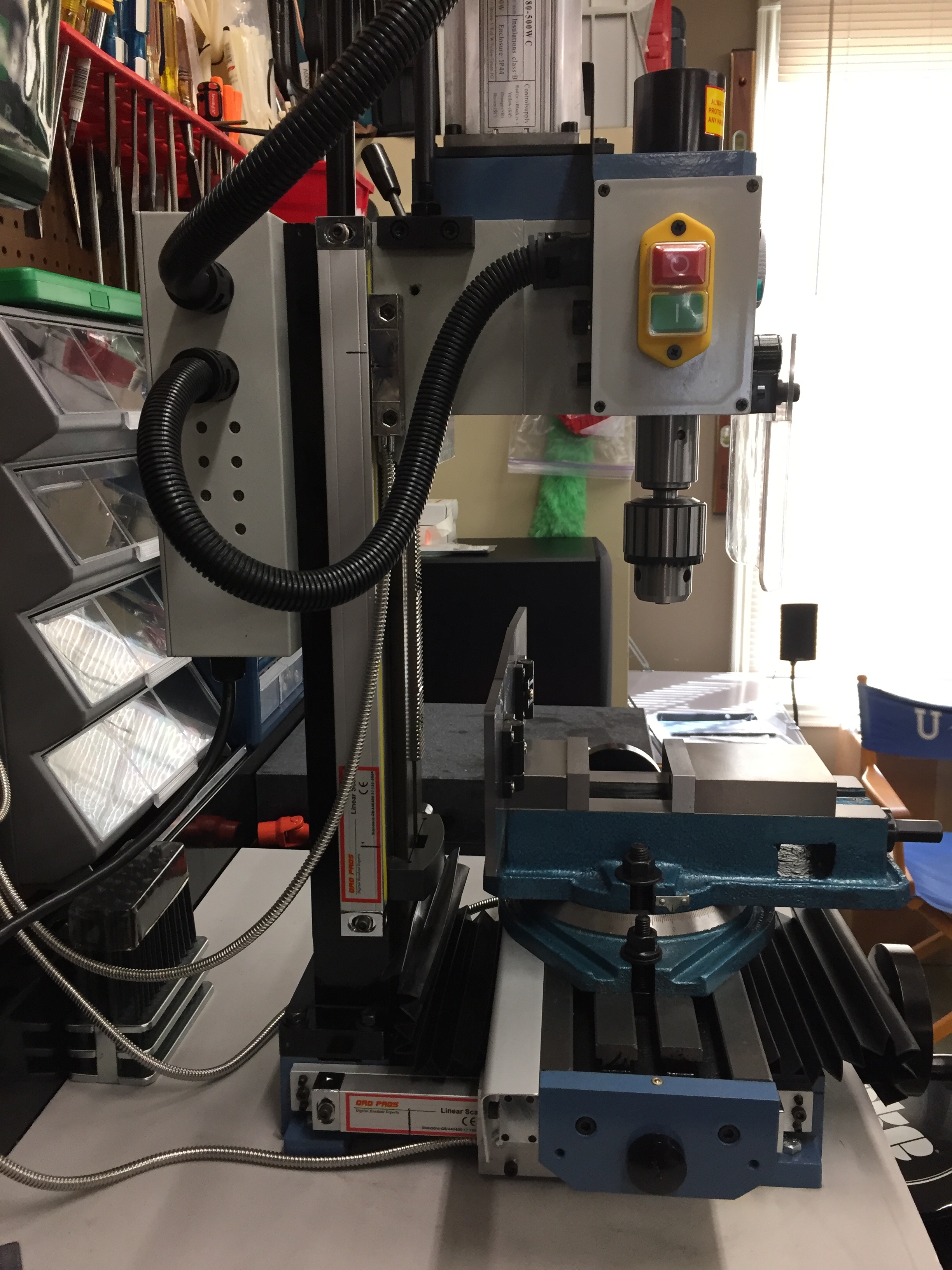
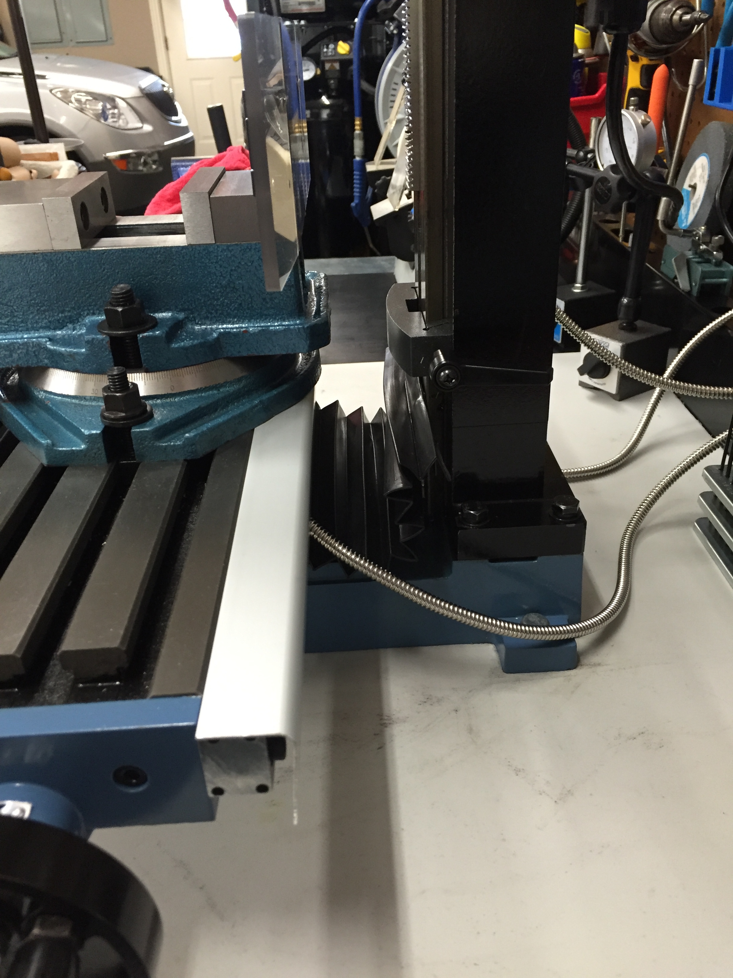
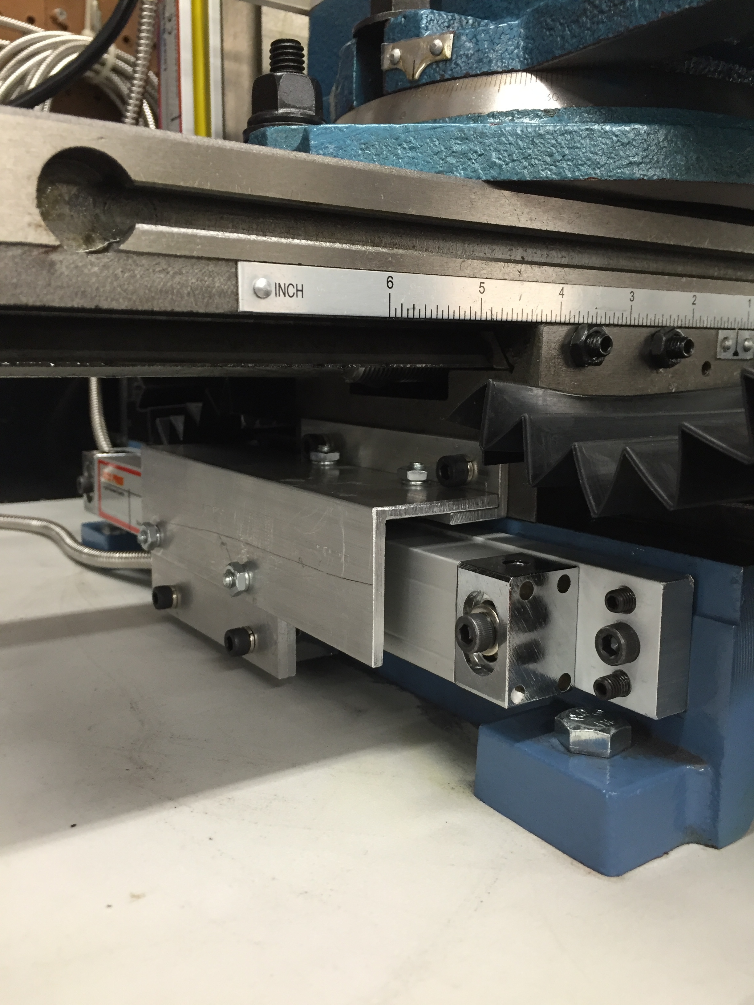
#11 - Courtesy
of B. Corneil with a DRO PROS Electronica Magnetic Scale Mill Kit:

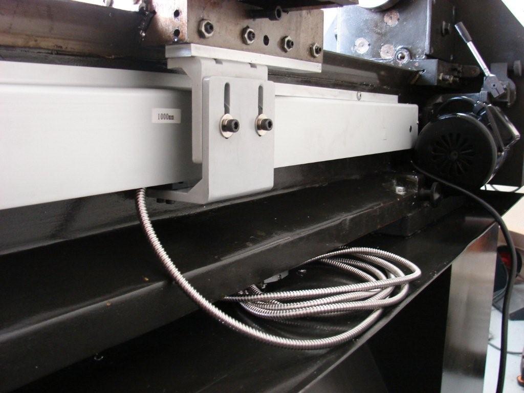
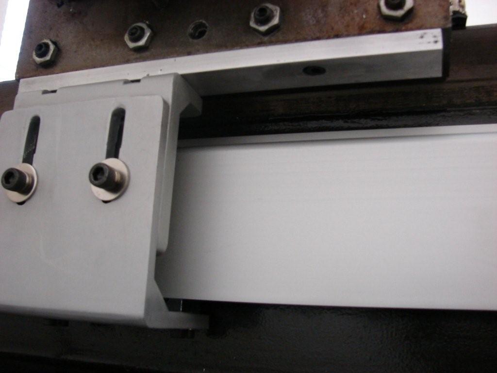
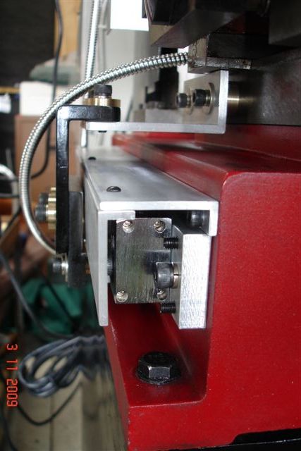
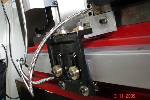
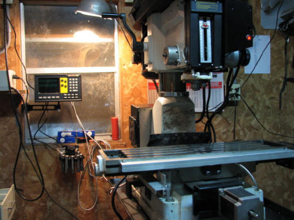
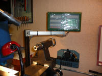
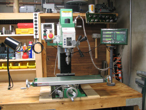
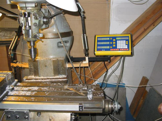
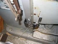
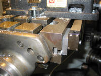
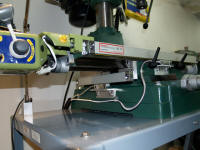
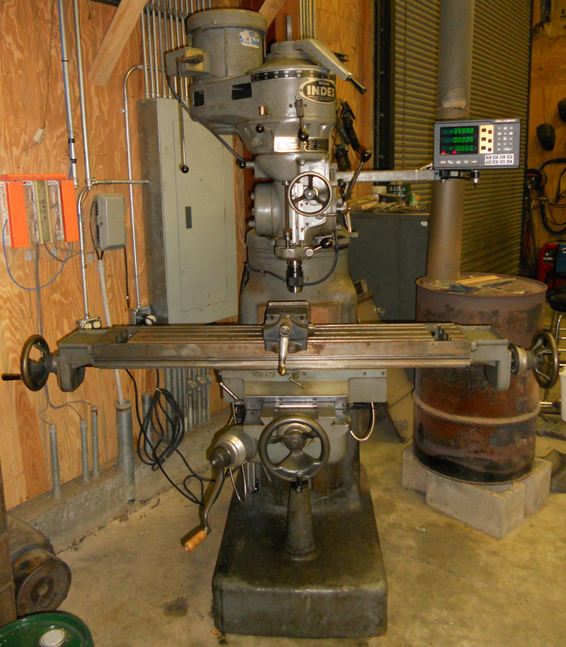
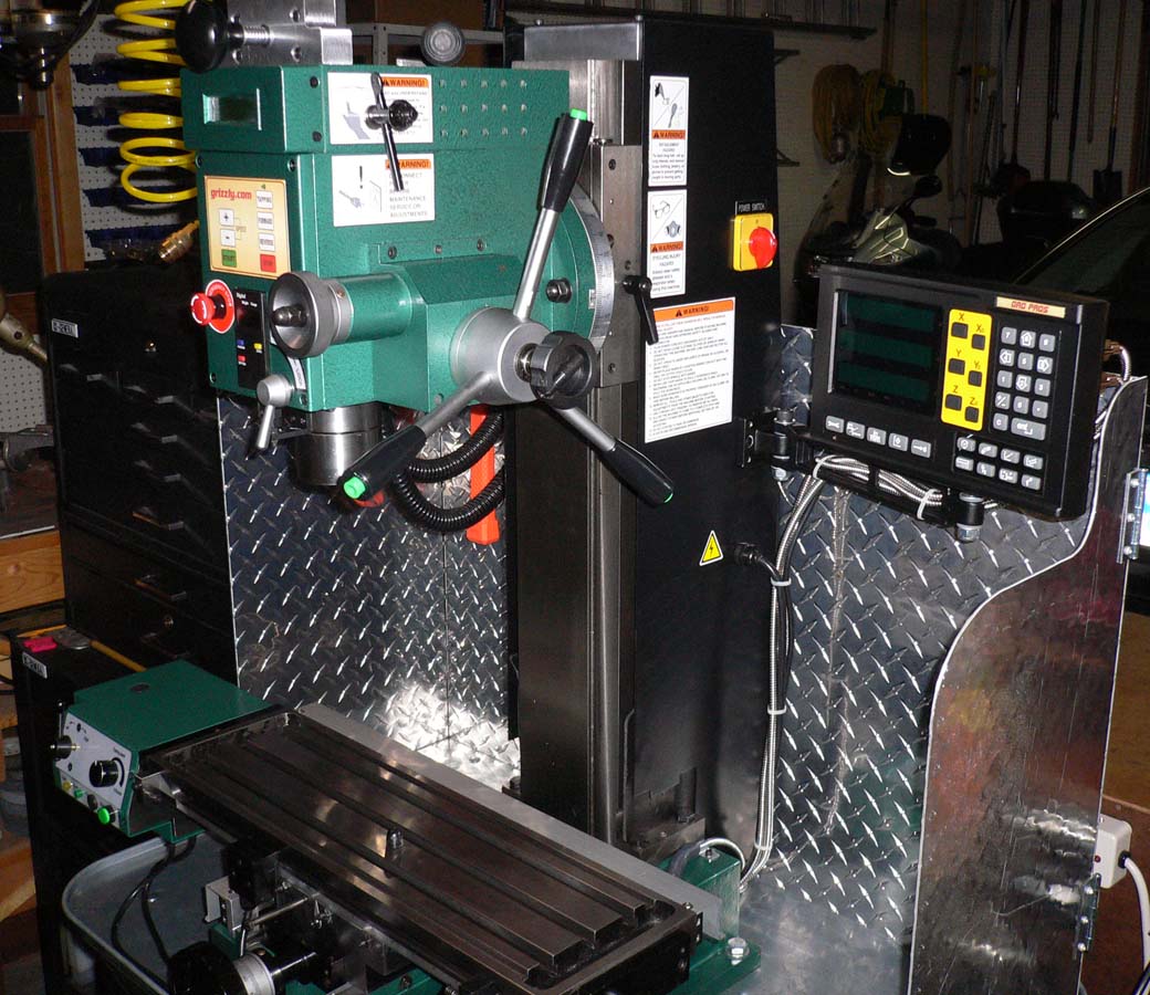
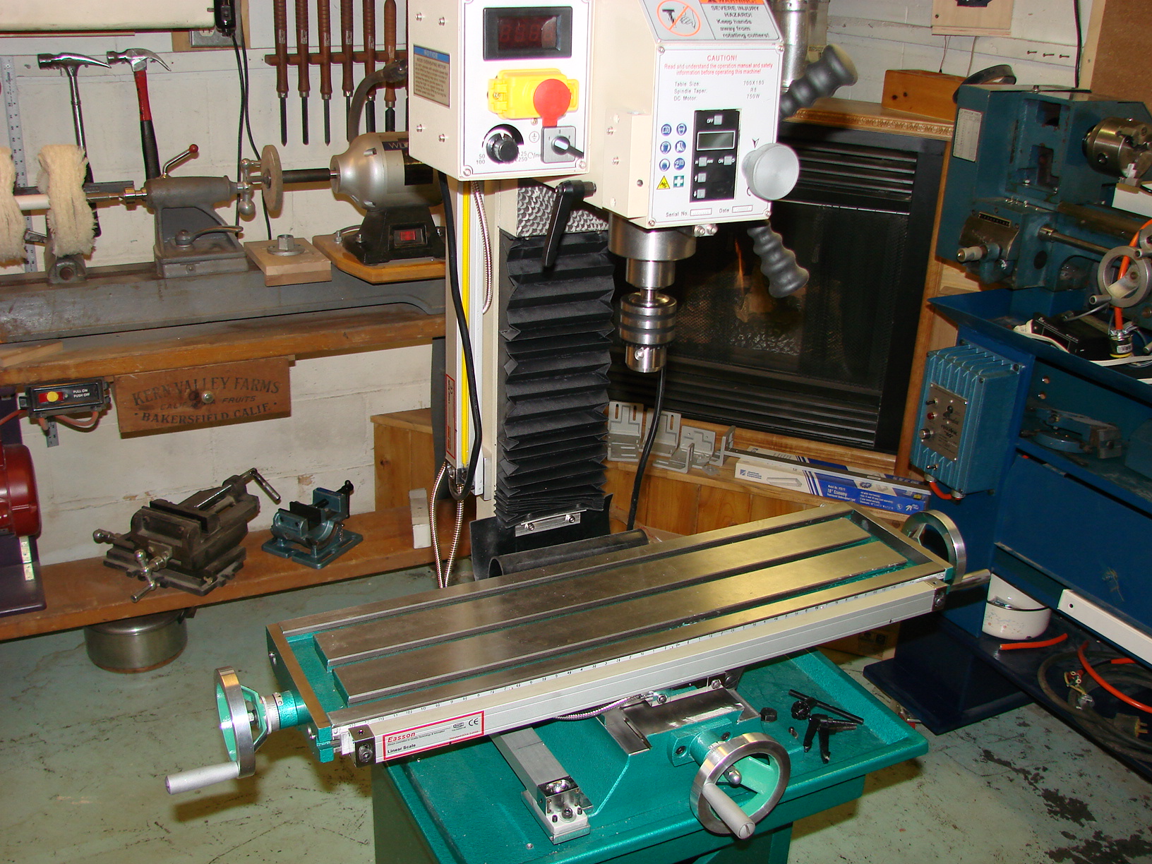
#12 - Courtesy
of B. Sly with a DRO PROS Electronica Magnetic Scale Mill Kit:
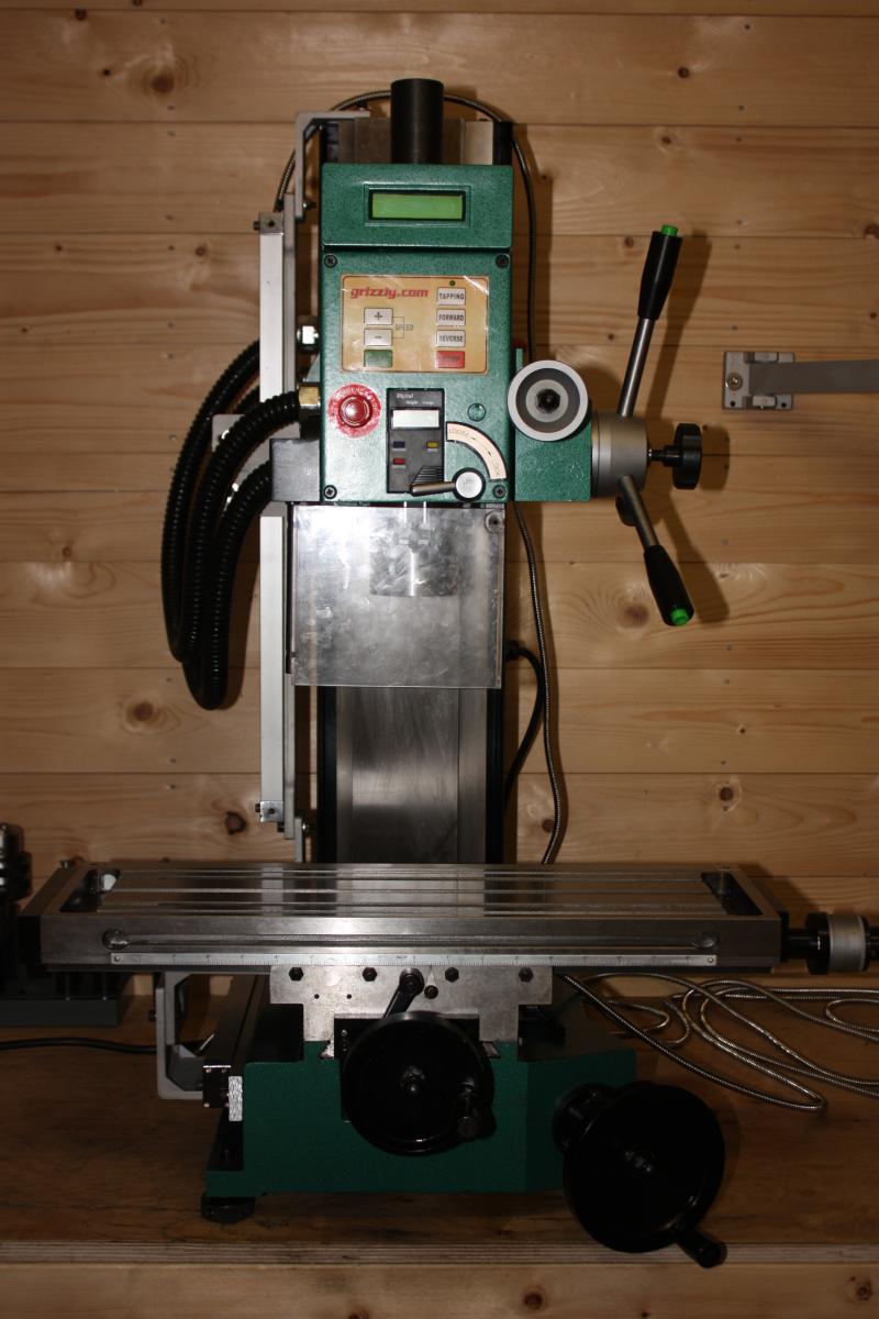
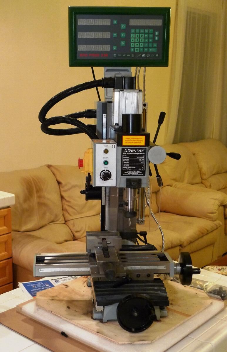
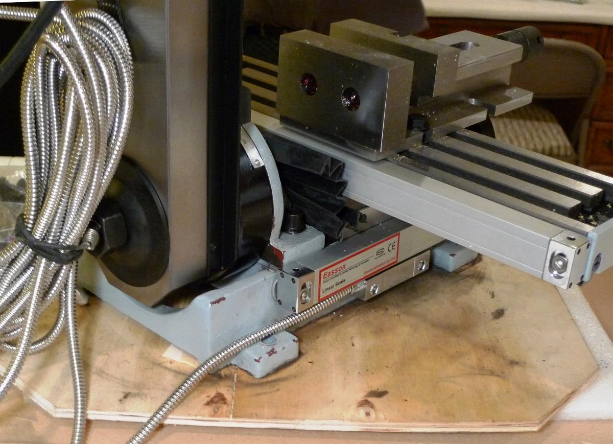
#13 - Courtesy
of B. Janacek with a DRO PROS Electronica Magnetic Scale Mill Kit:

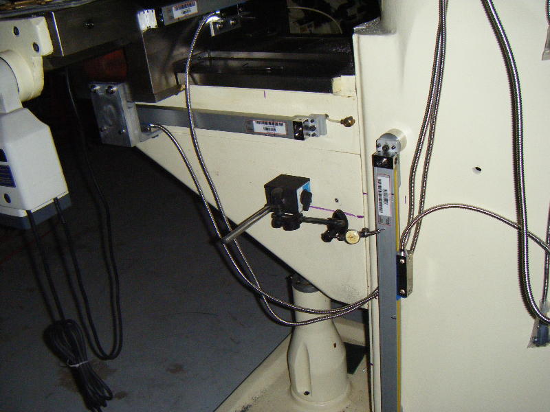
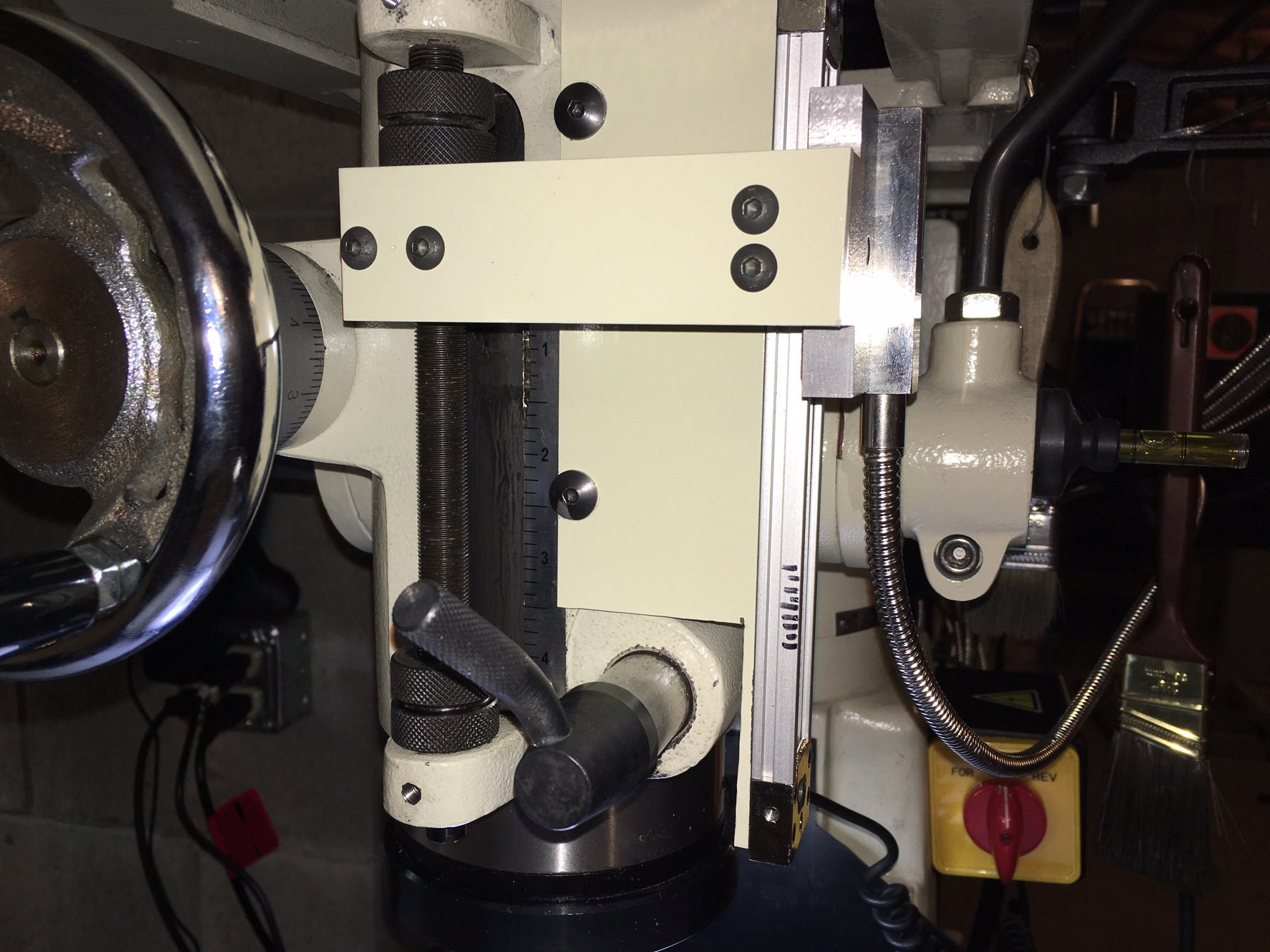
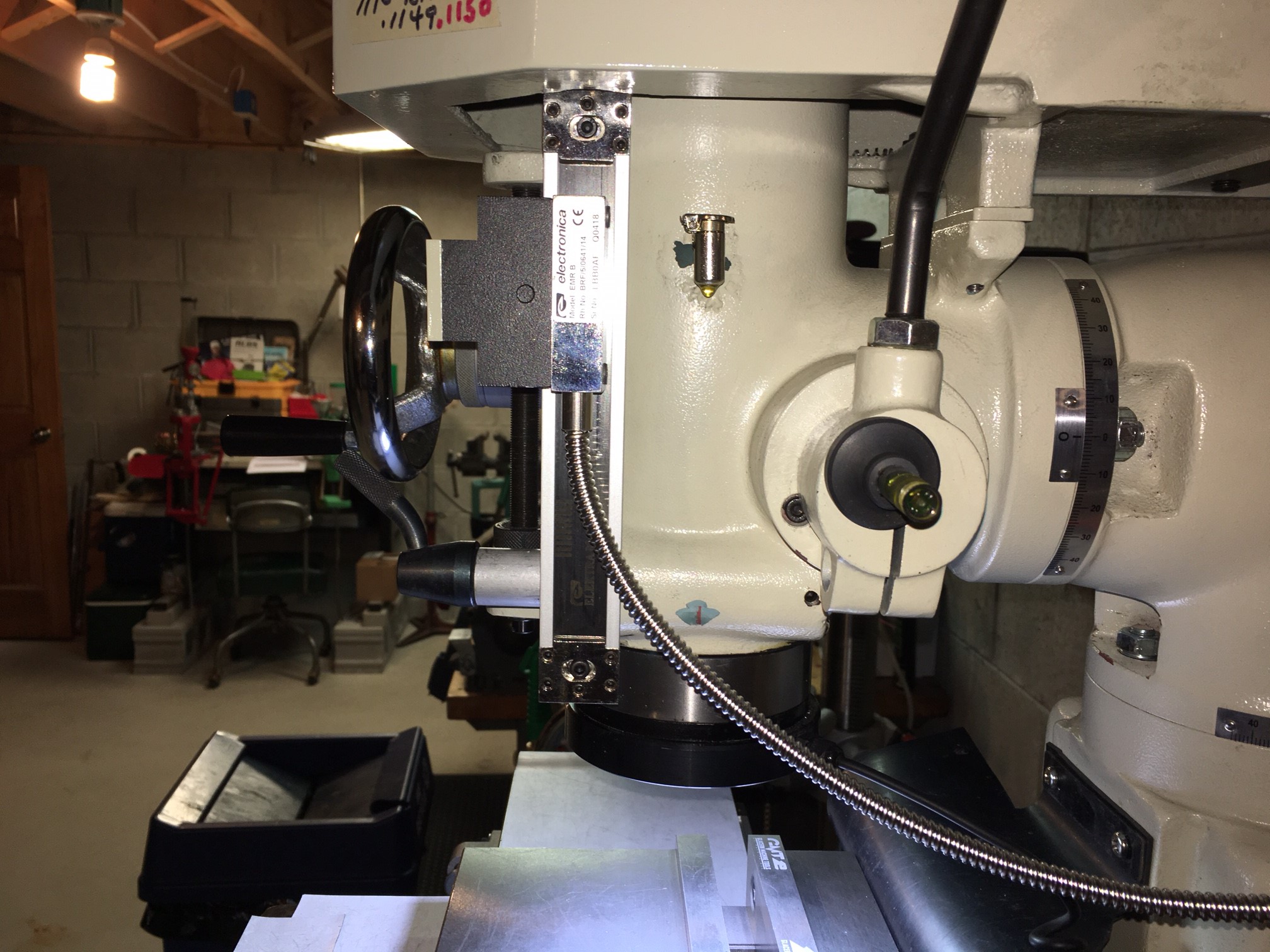
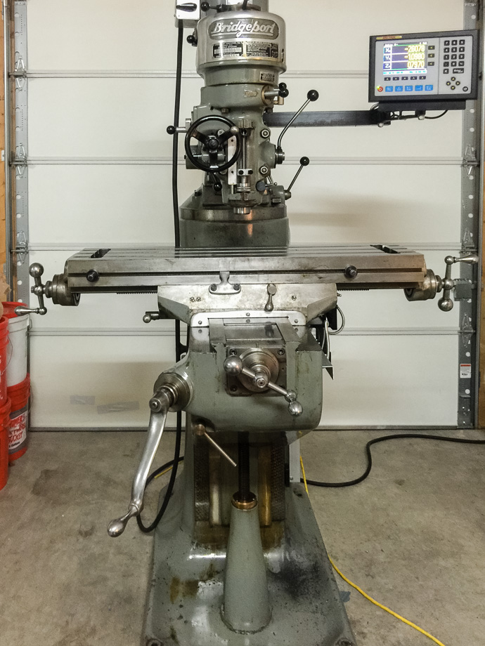
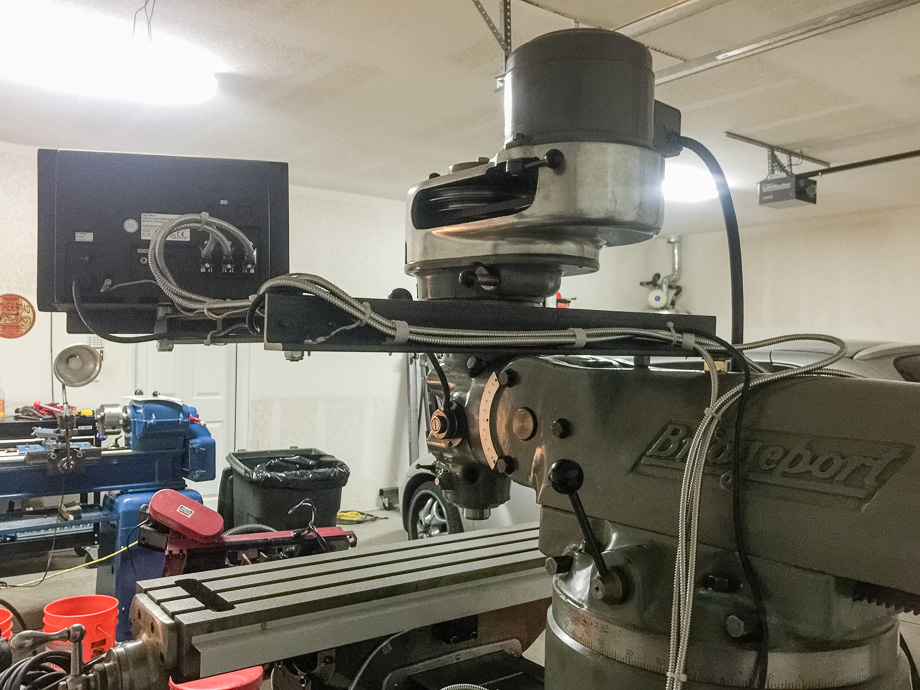
#14 - Courtesy
of K. Rucker with a DRO PROS Electronica Magnetic Scale Mill Kit:

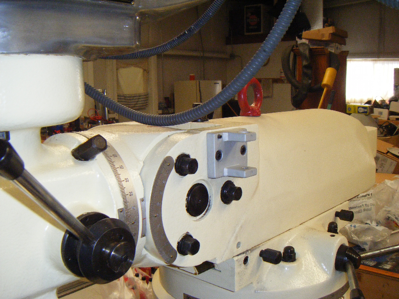
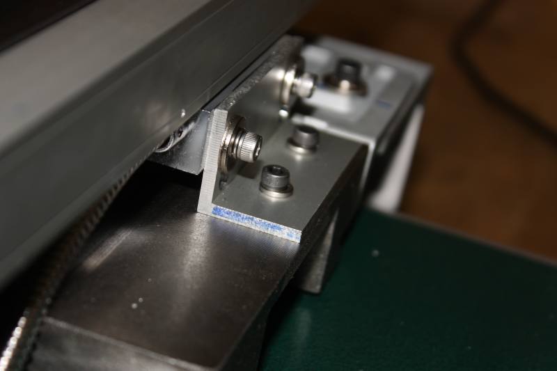
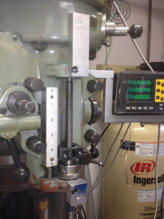
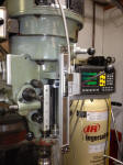
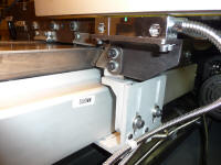
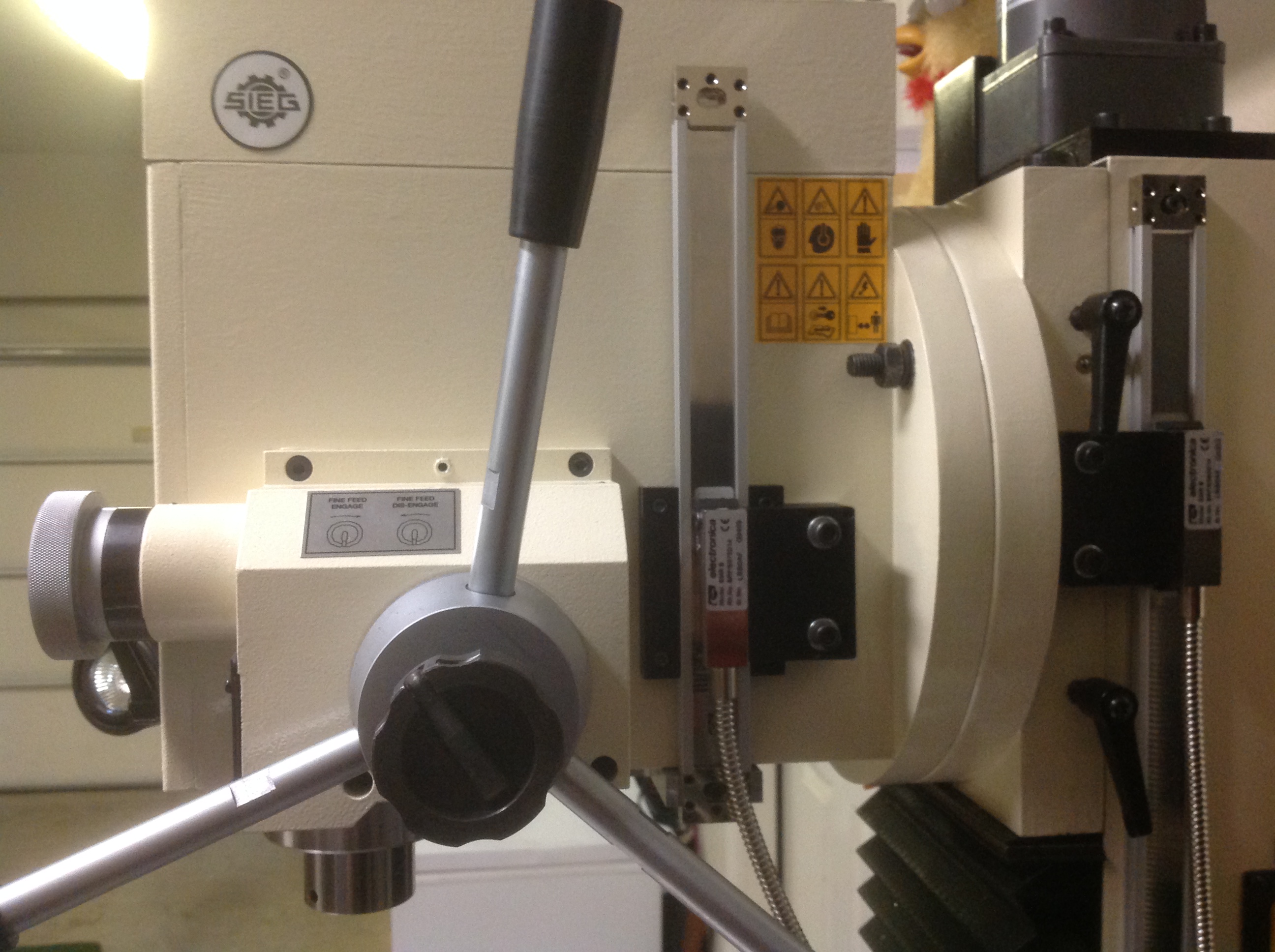
#15 - Courtesy
of D. Ticehurst with an Electronica Magnetic Scale Mill Kit on the quill:
#16 - Courtesy
of M. Tracy with a DRO PROS Electronica Magnetic Scale Lathe Kit:
  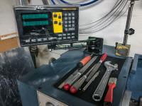
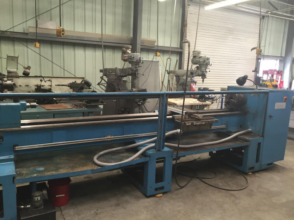
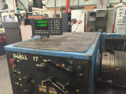
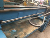
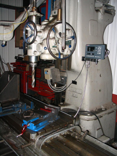
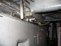
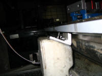
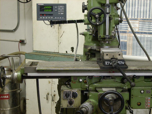
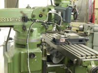
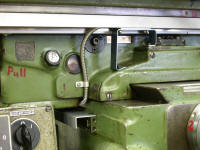
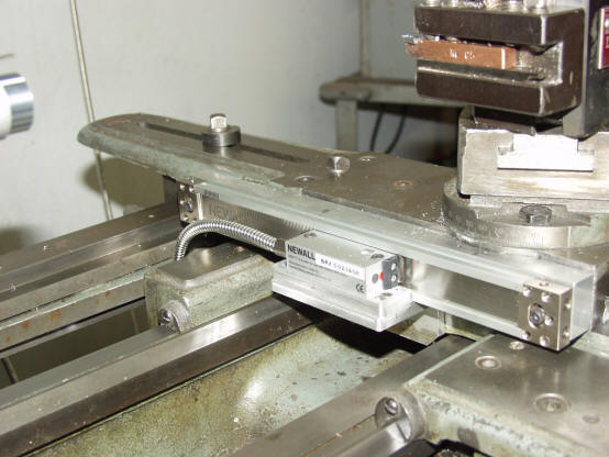
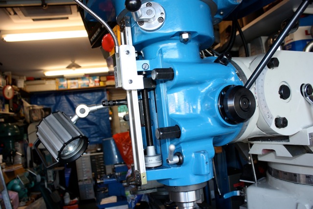
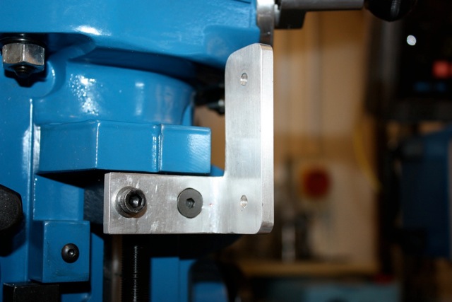
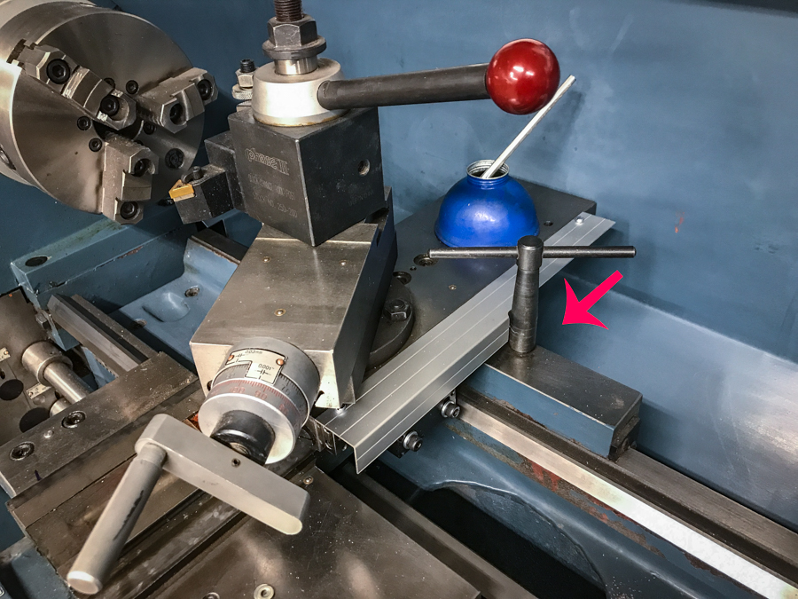
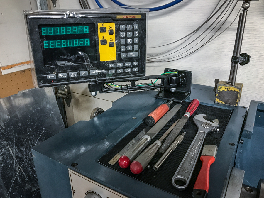
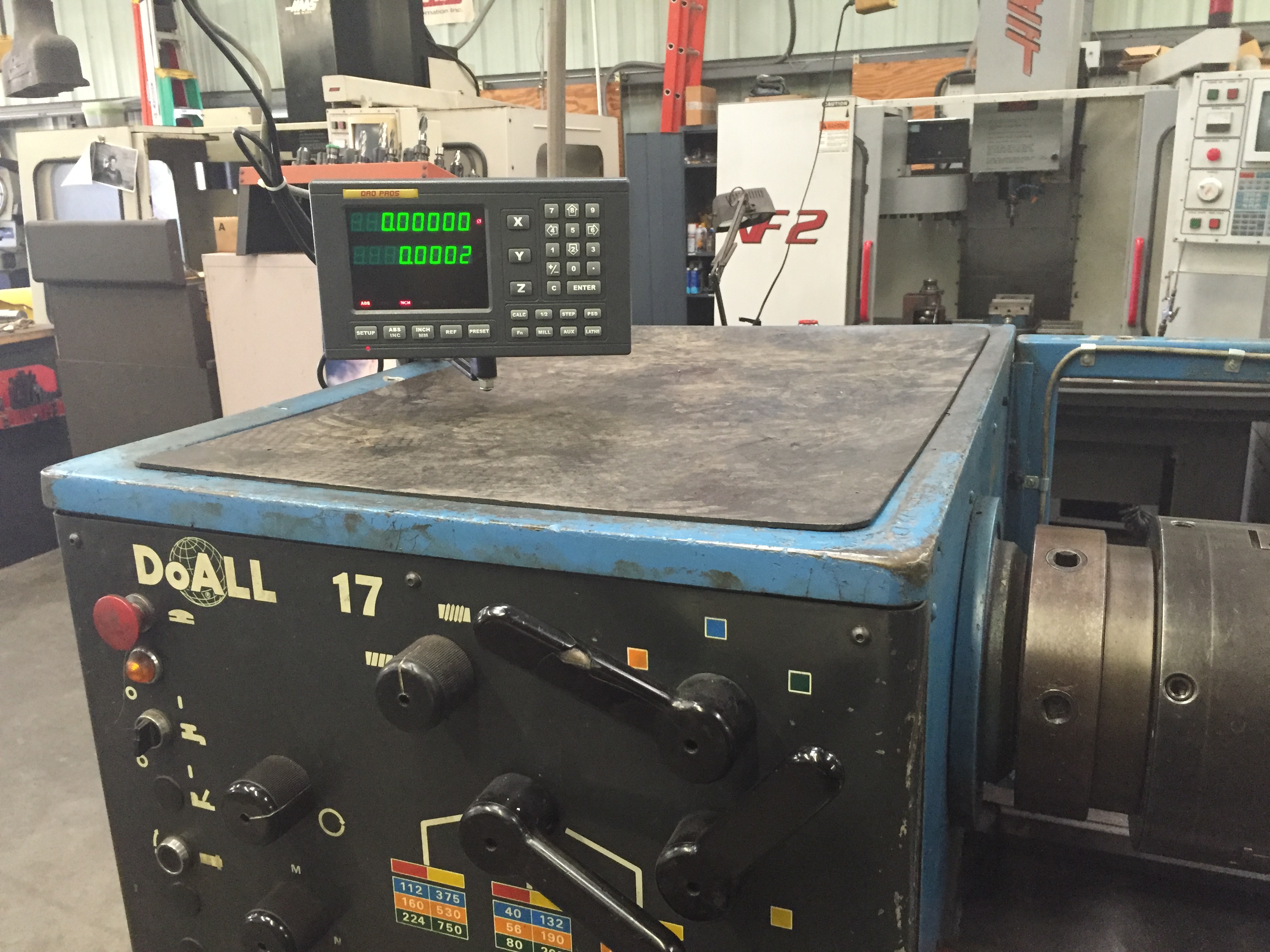
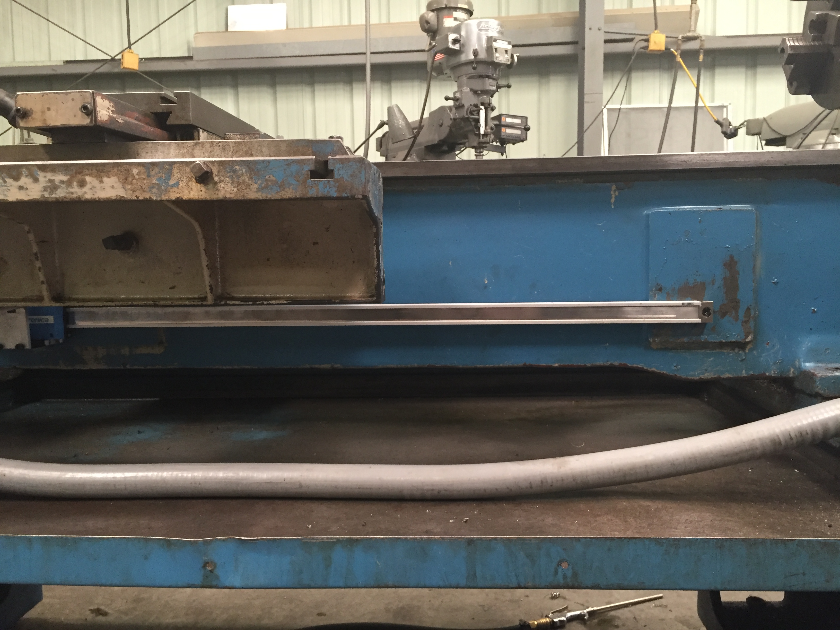
#17 - Courtesy
of J. Maxwell with a DRO PROS Electronica Magnetic Scale Lathe Kit:
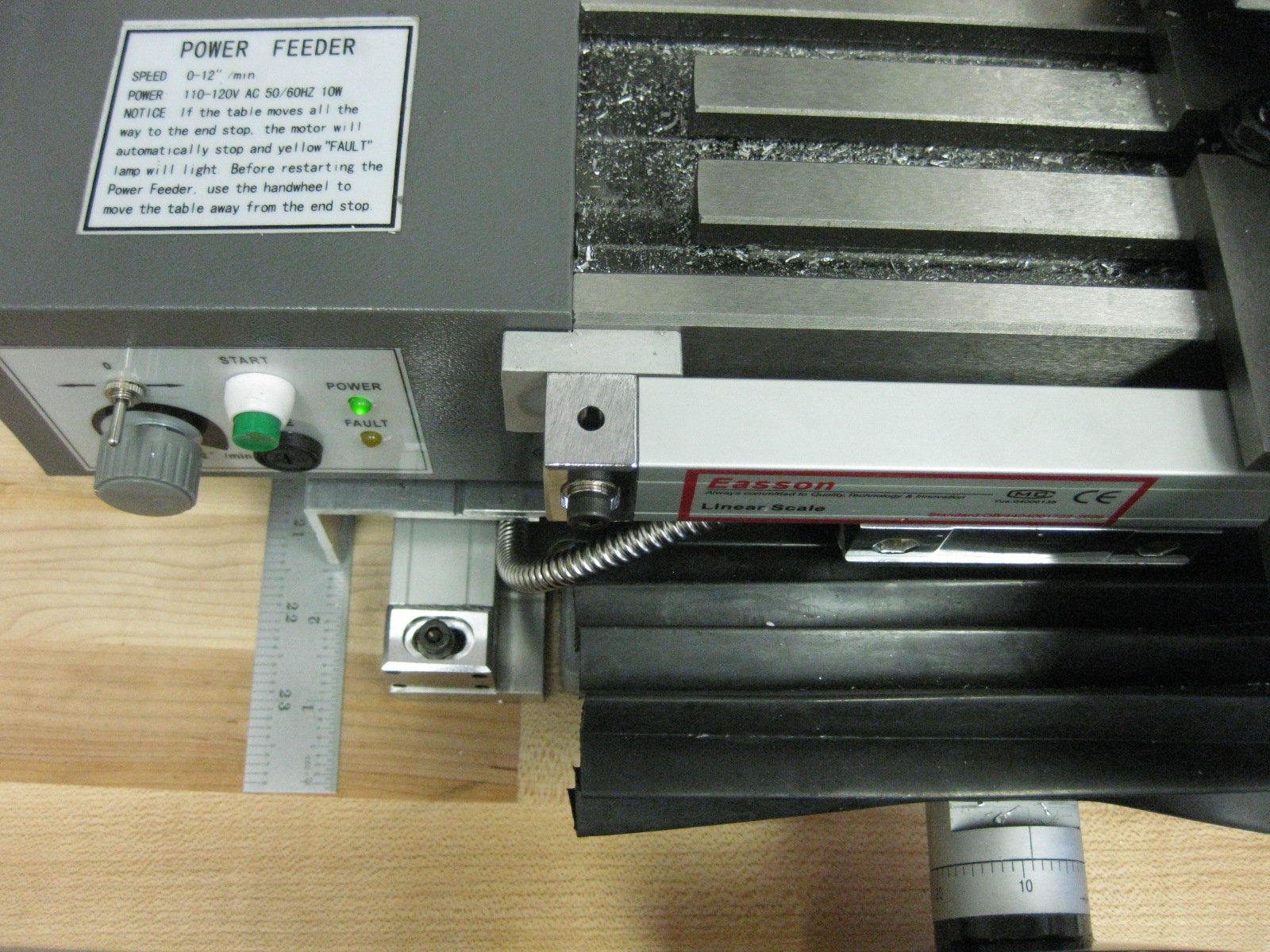
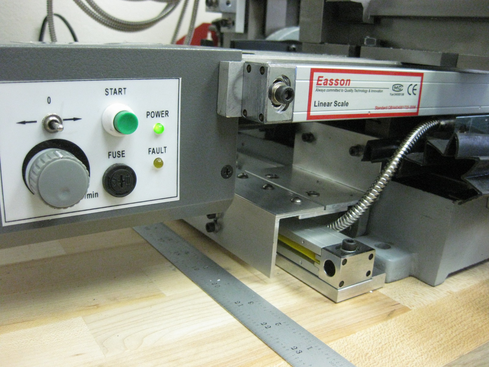
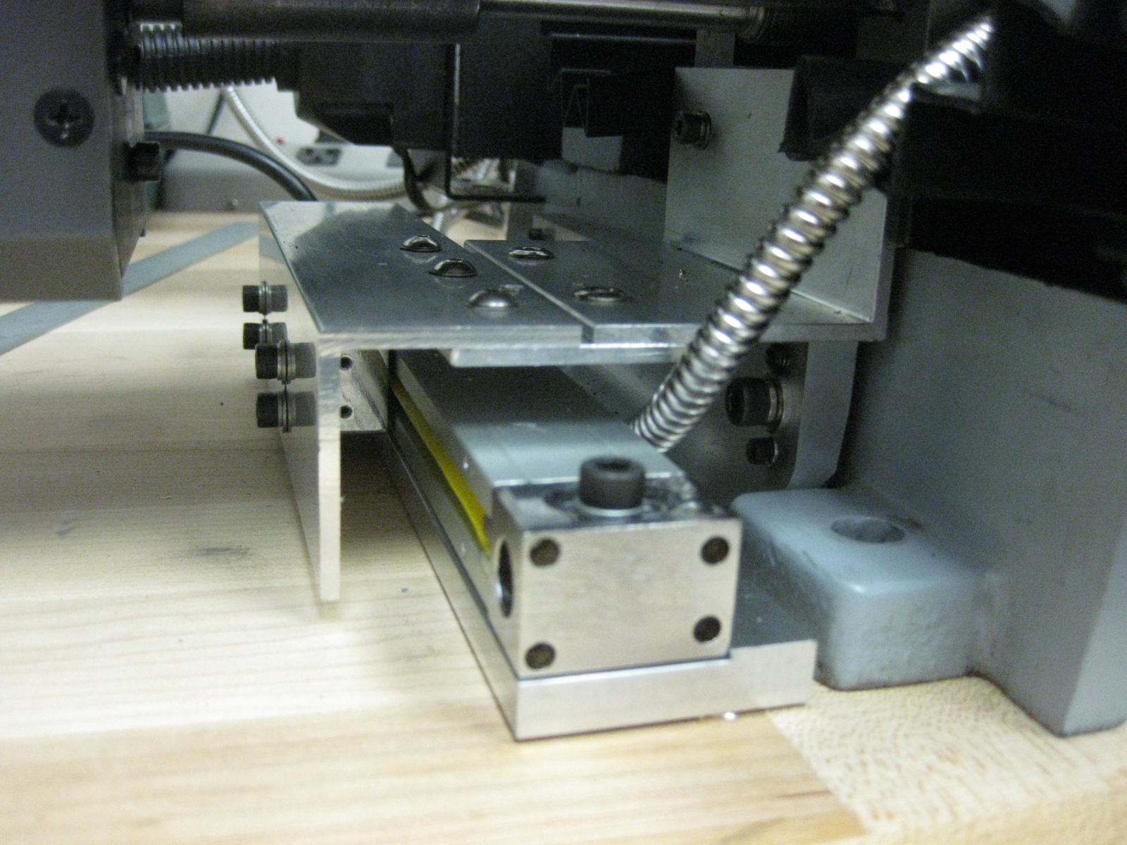
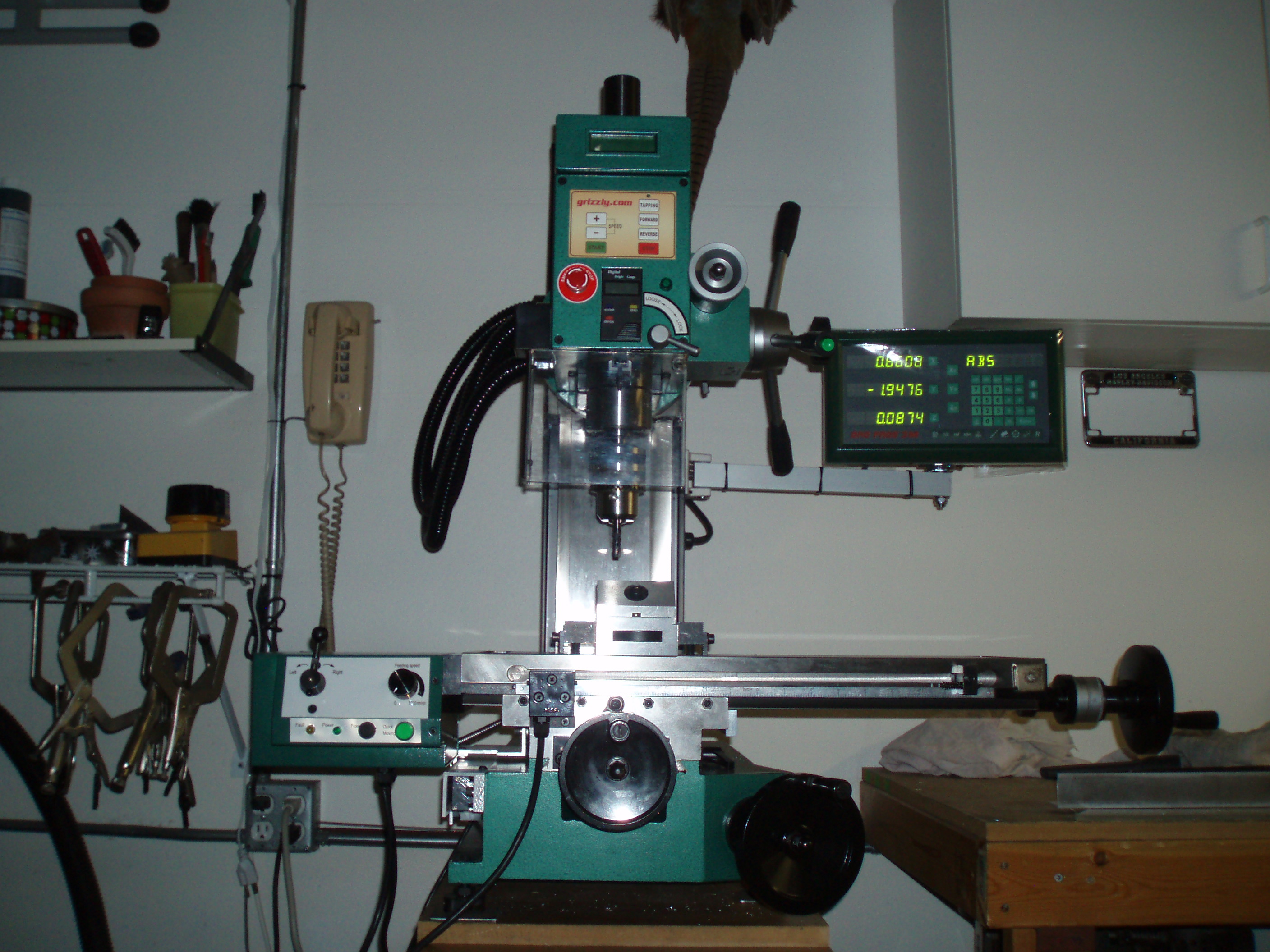
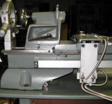
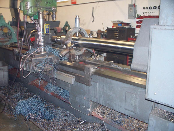
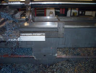
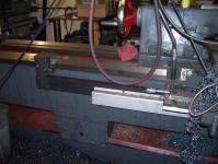
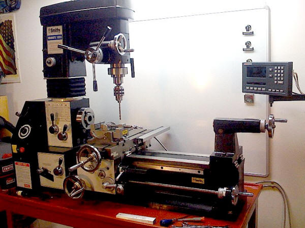
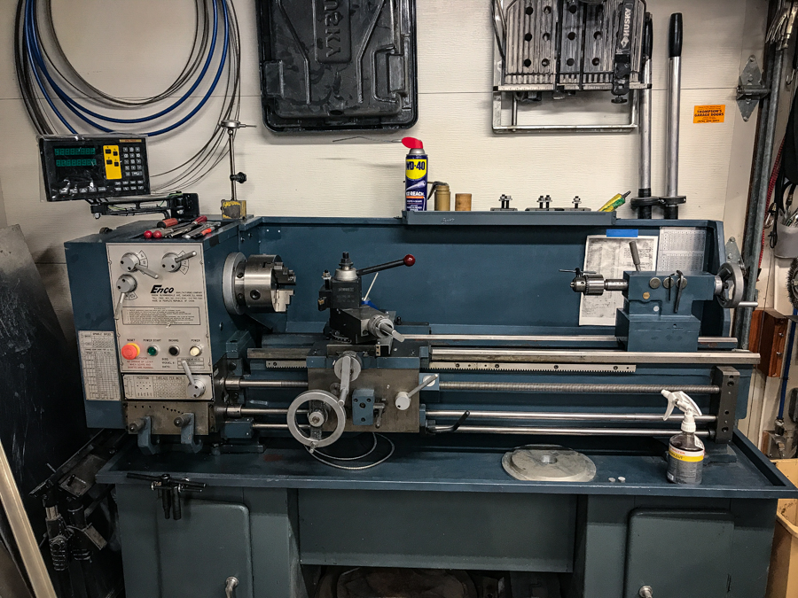
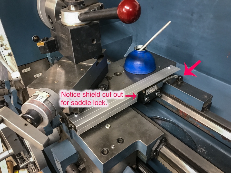
#18 - Courtesy
of J. Morrison with a DRO PROS Electronica Magnetic Scale Lathe Kit:

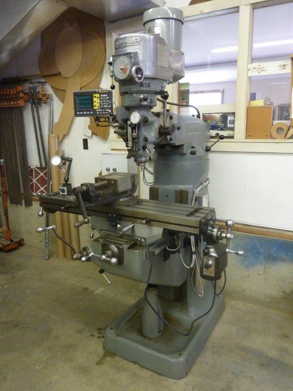
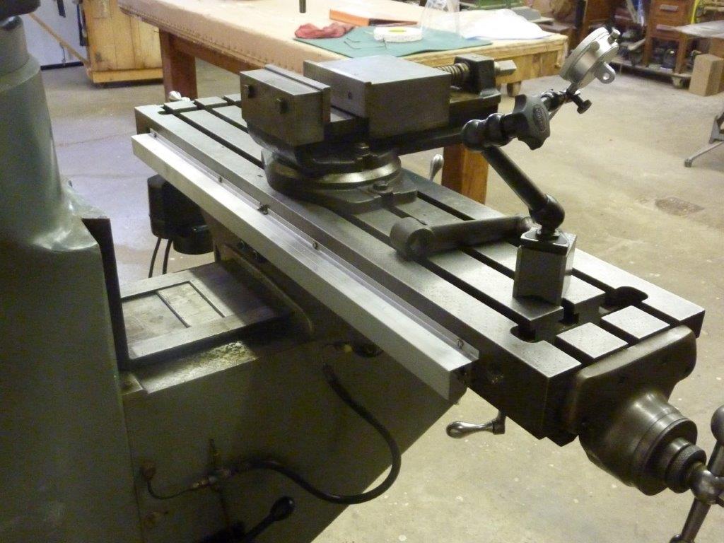
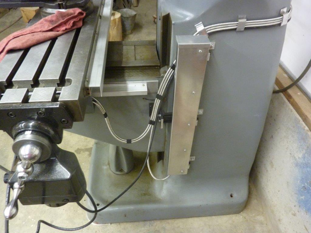
#19 - Courtesy
of L. Schmidt with an Electronica 4 Axis Magnetic Scale Mill Kit:
#20 - Courtesy
of J. Gilmore with a DRO PROS Electronica Magnetic Scale Mill Kit:
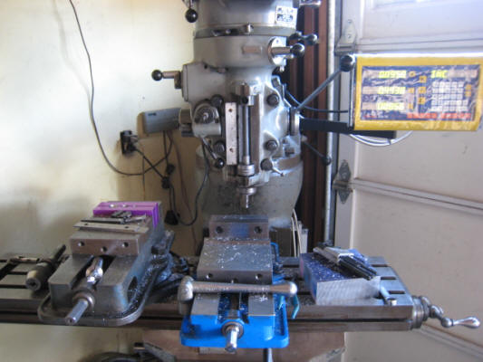
#21 - Courtesy
of A. McCutchen with an Electronica EL400 Magnetic Scale Mill Kit:
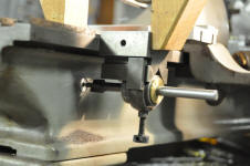
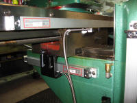
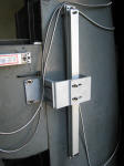
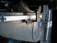
#22 - Courtesy
of Mitch with a Magnetic EL400 on his lathe:
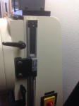
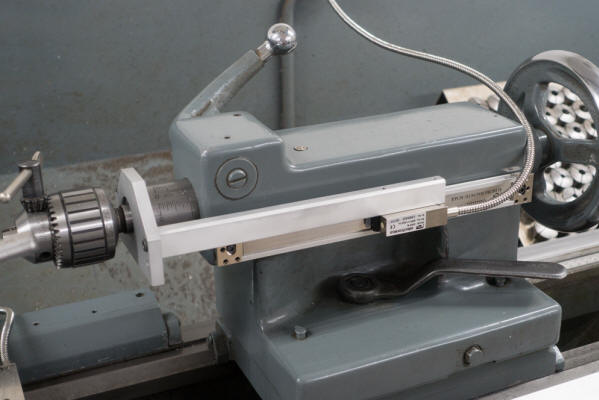
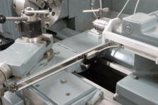
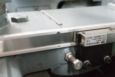
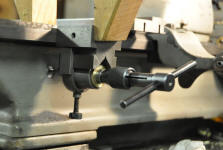
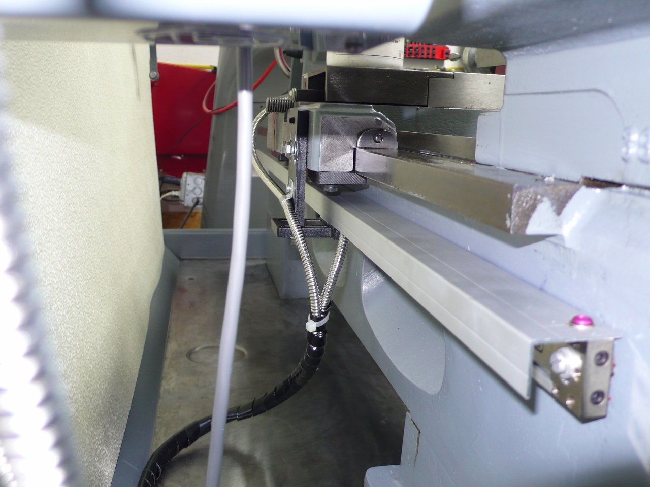
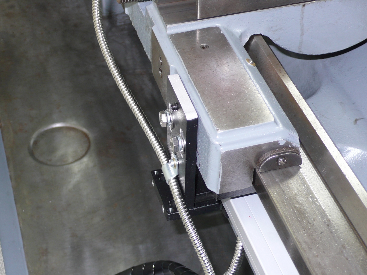
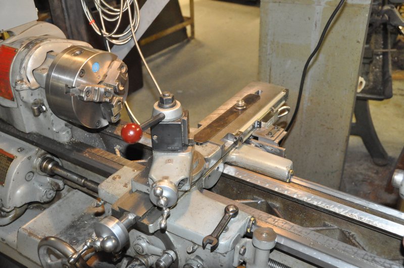
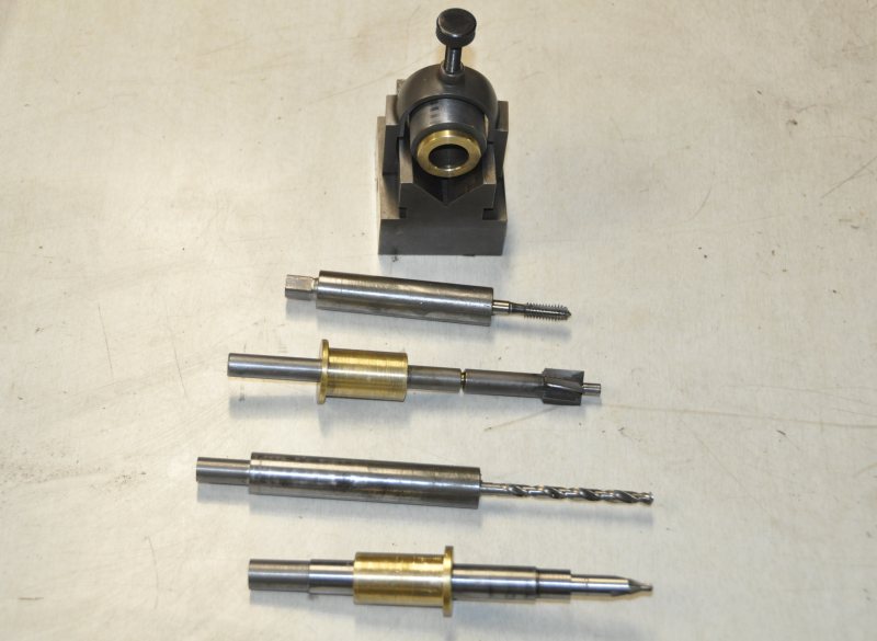
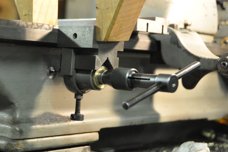
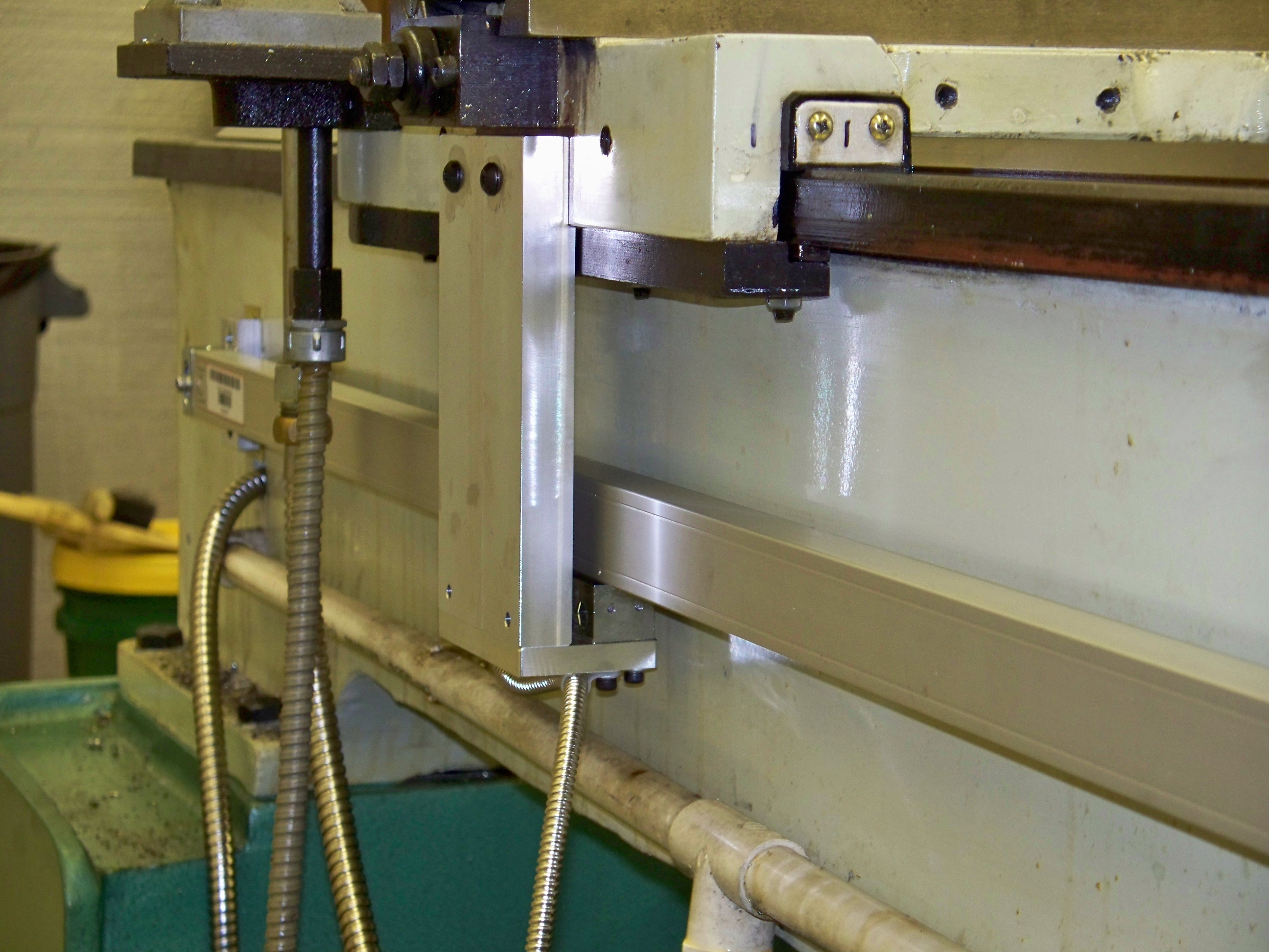
#23 - Courtesy
of Anonymous with a Magnetic Scale on the tailstock:
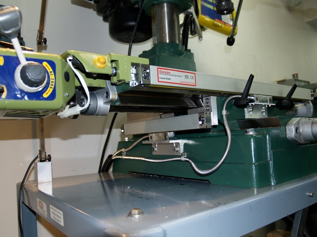
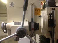
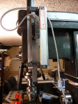
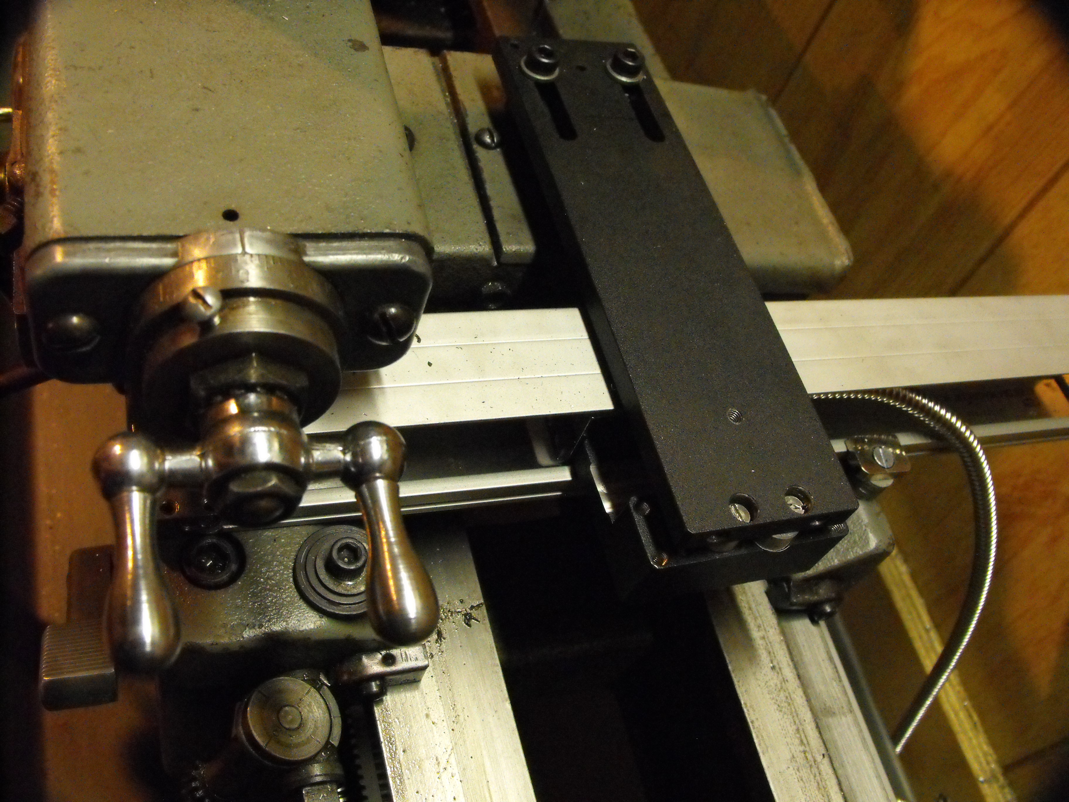
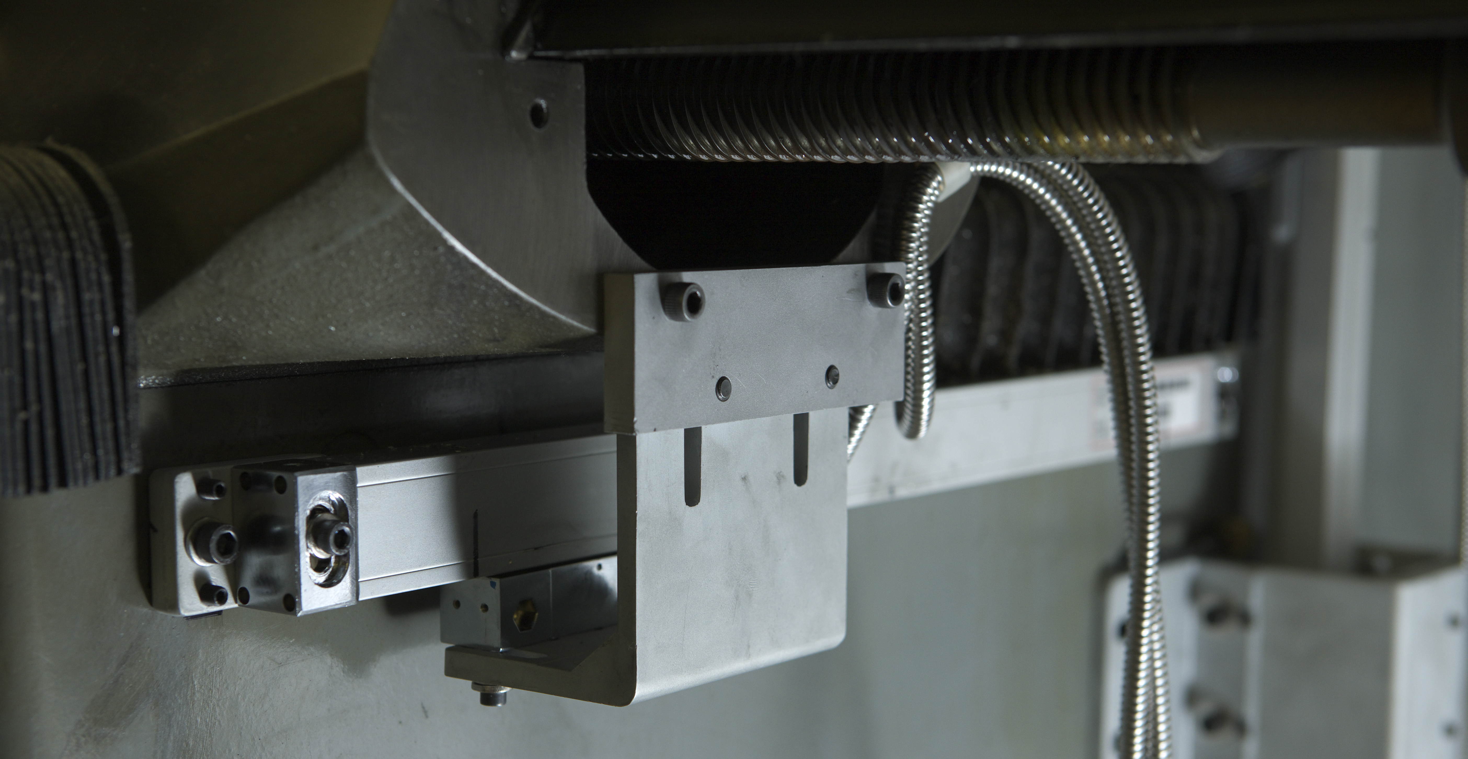
#24 - Courtesy
of R. Molho with a 4 axis DRO PROS Magnetic Scale Quill:
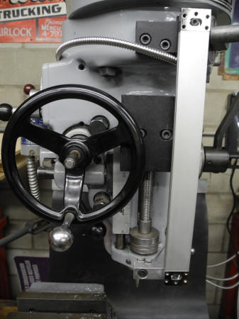
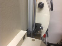
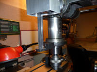
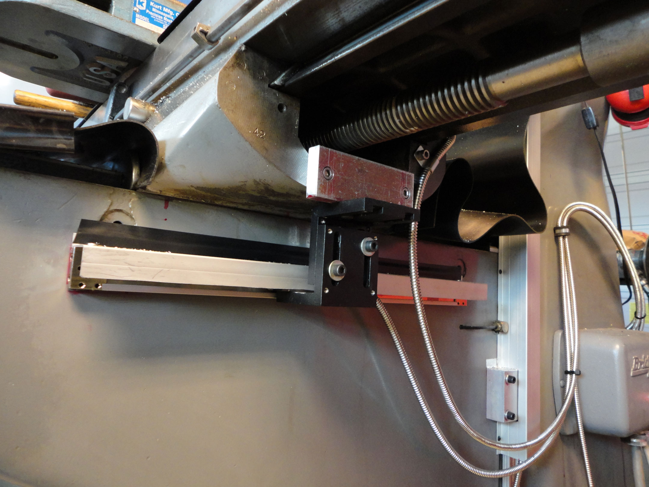
#25 - Courtesy
of W. Lane with a 4 axis DRO PROS Magnetic Scale Quill:
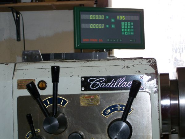
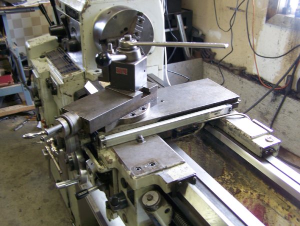
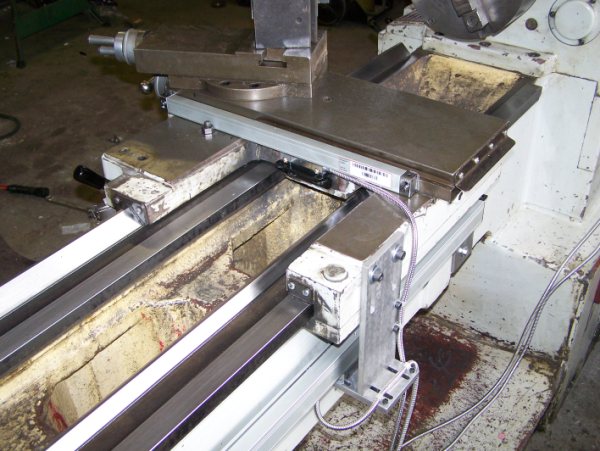
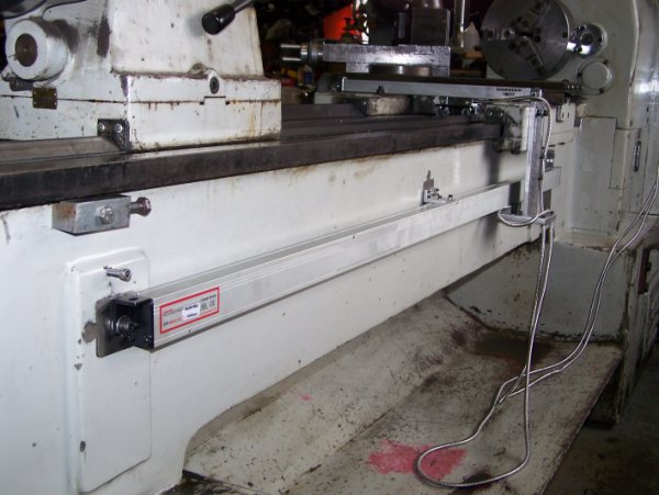
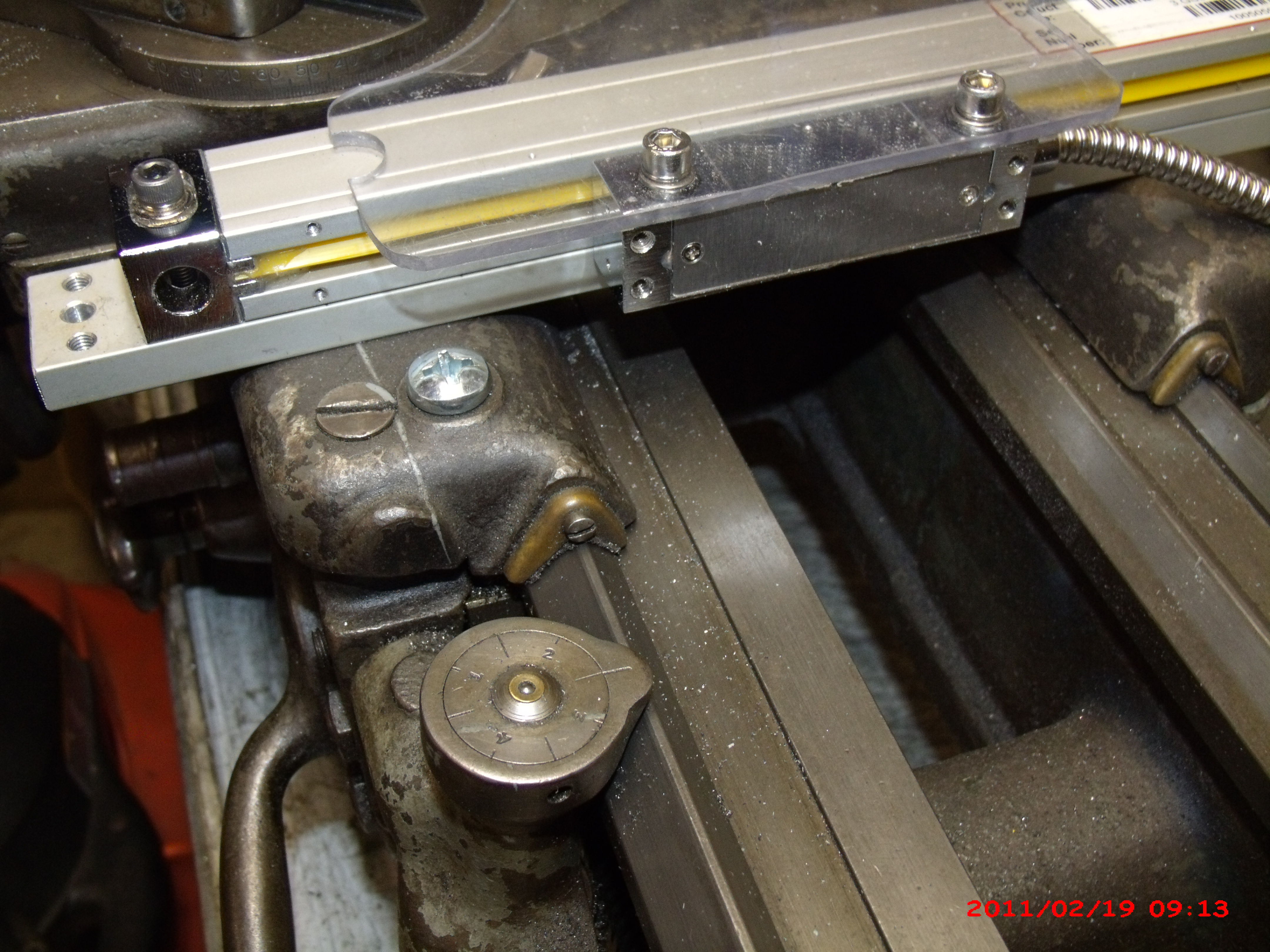
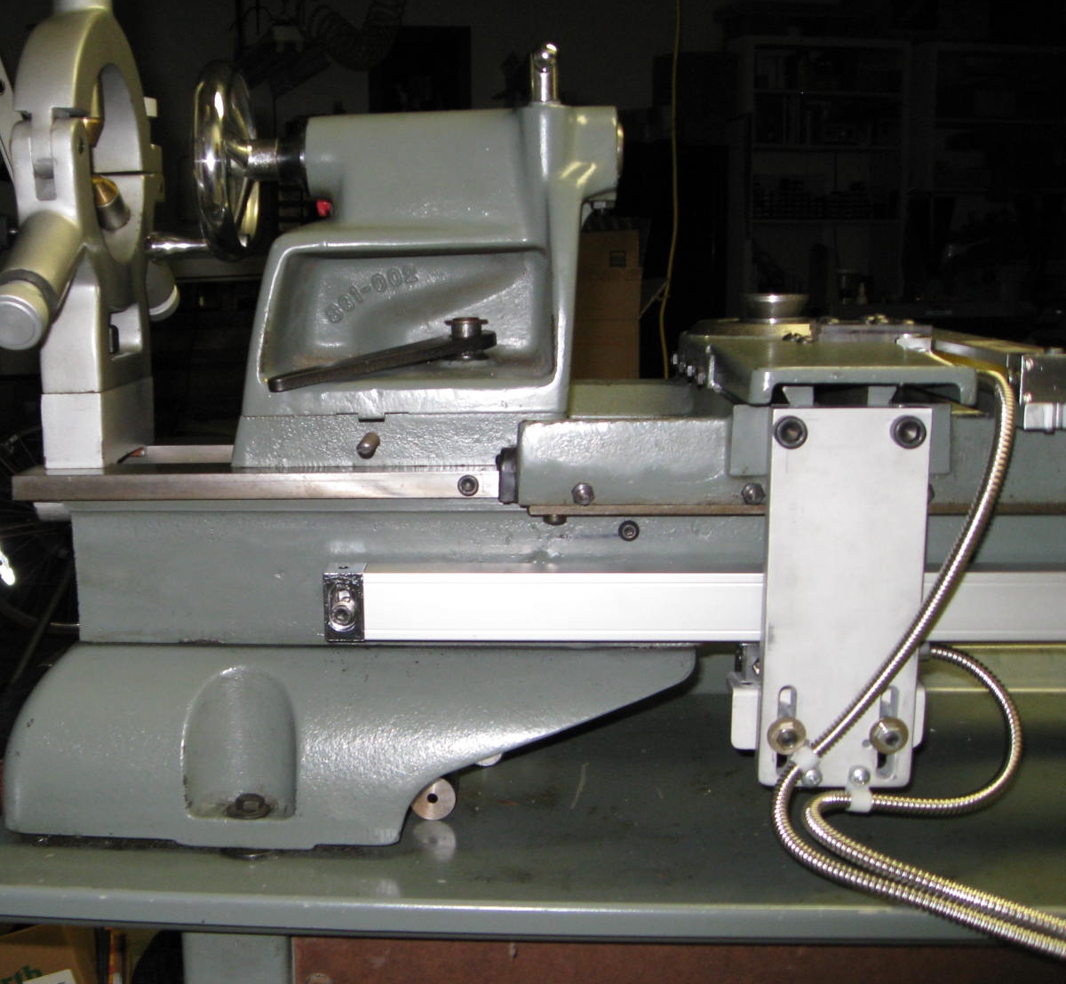
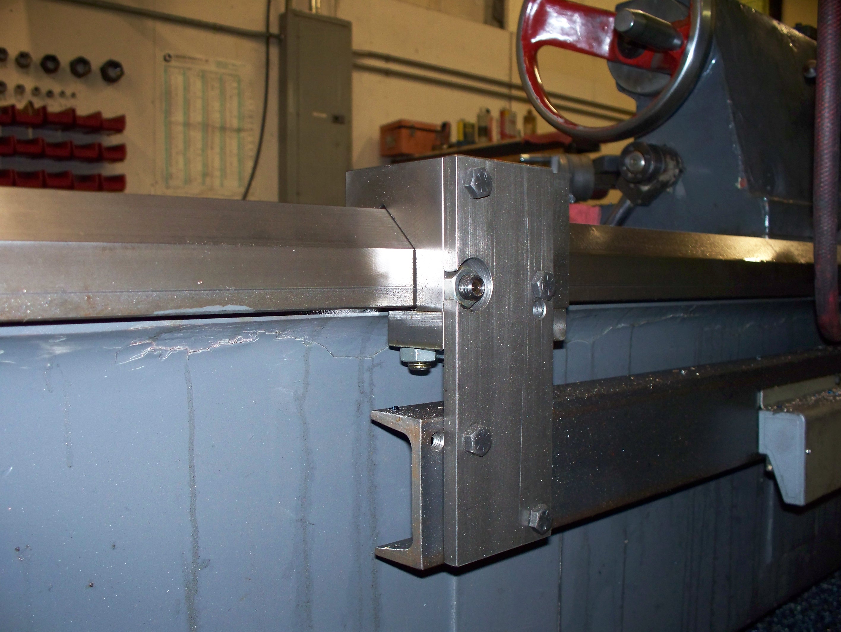
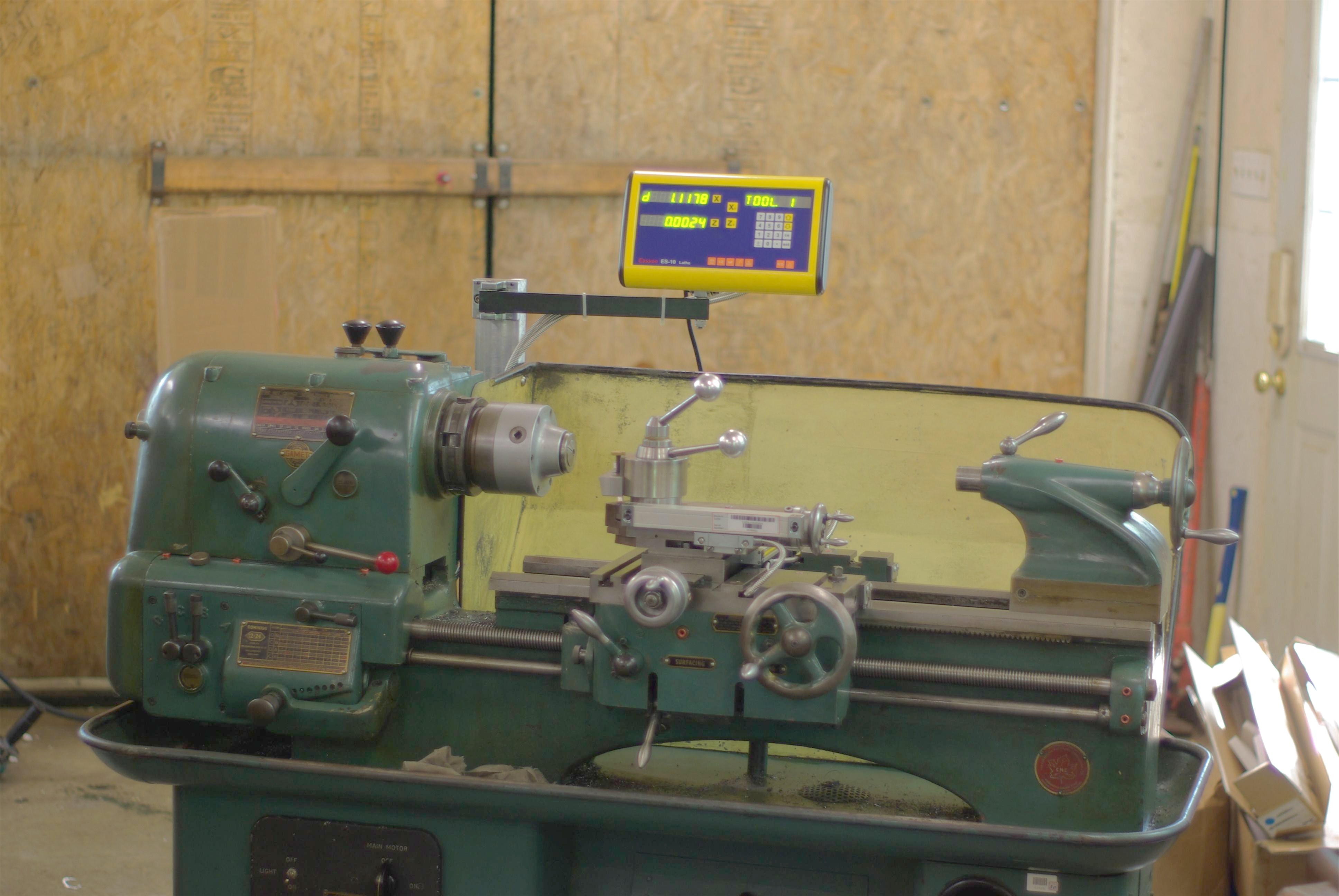
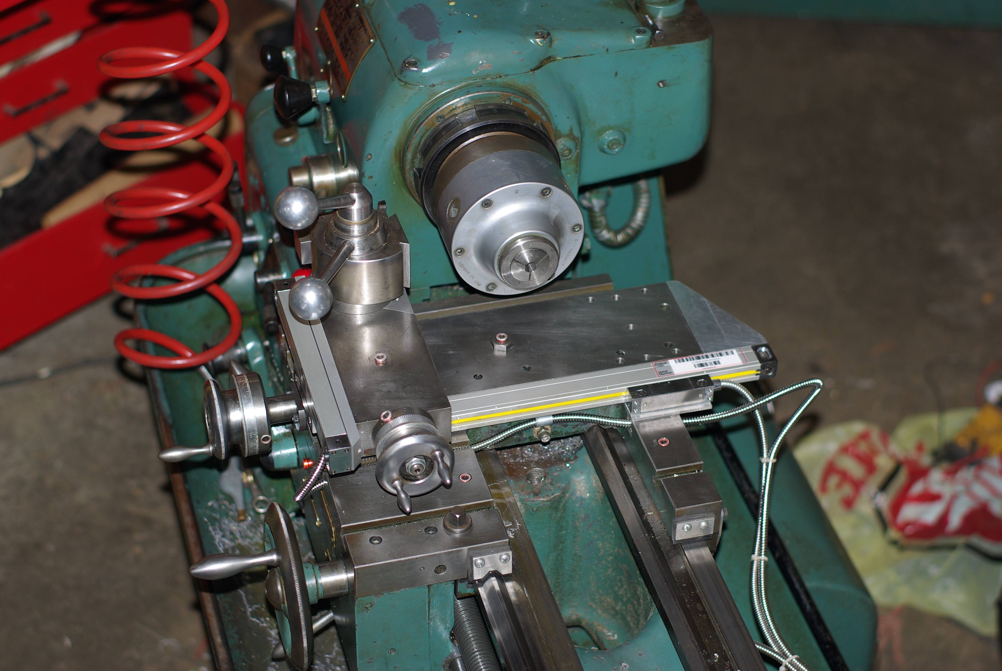
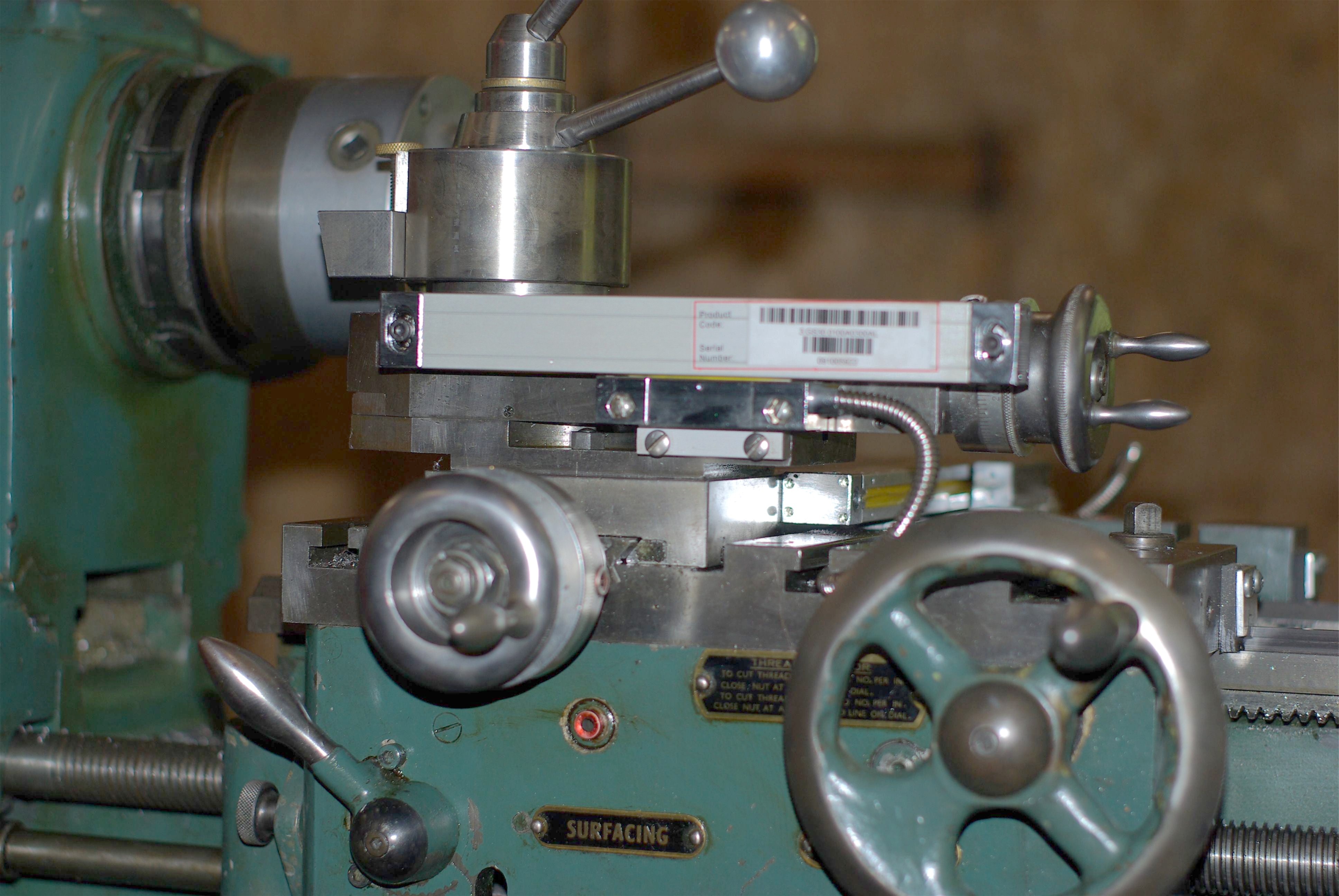
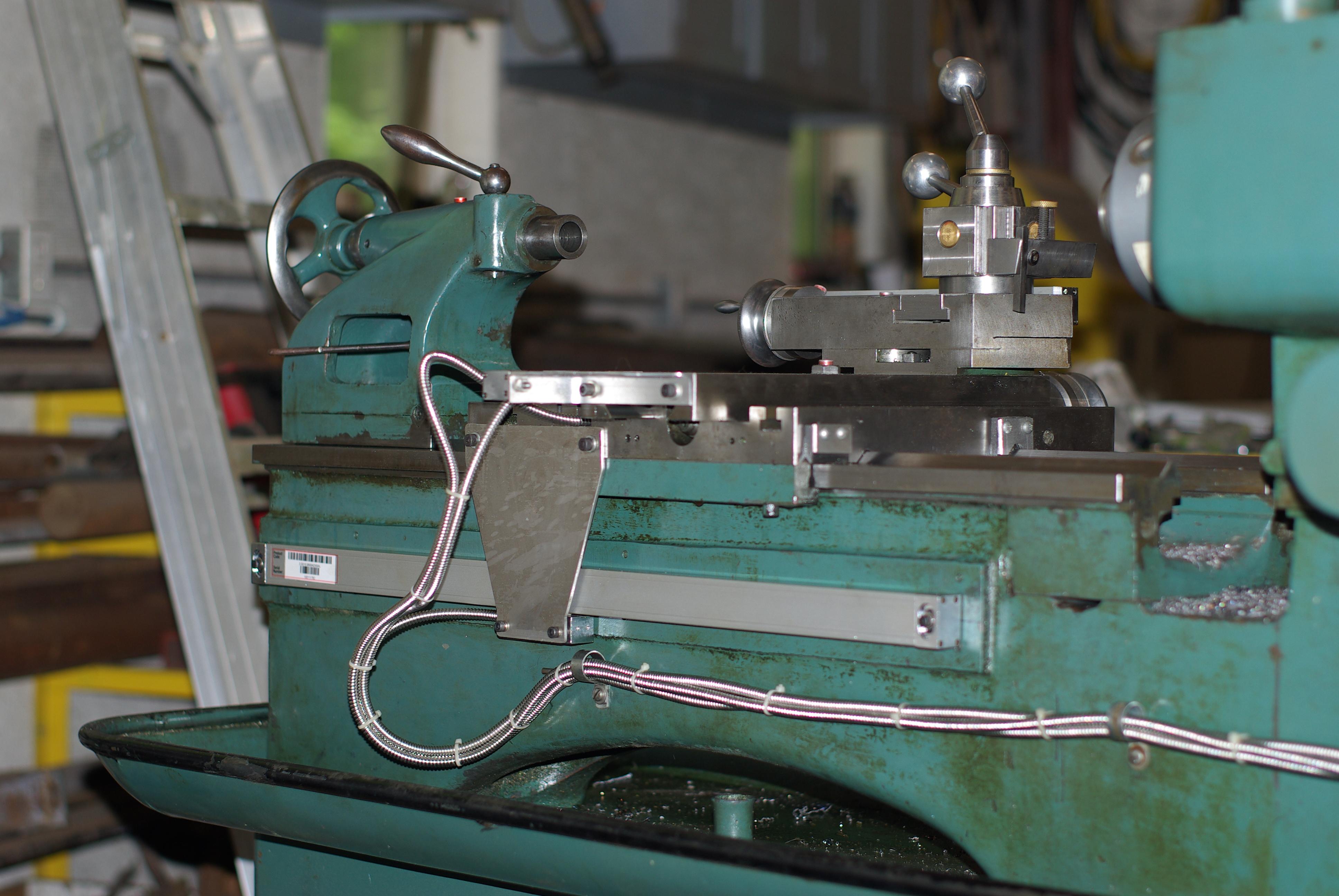
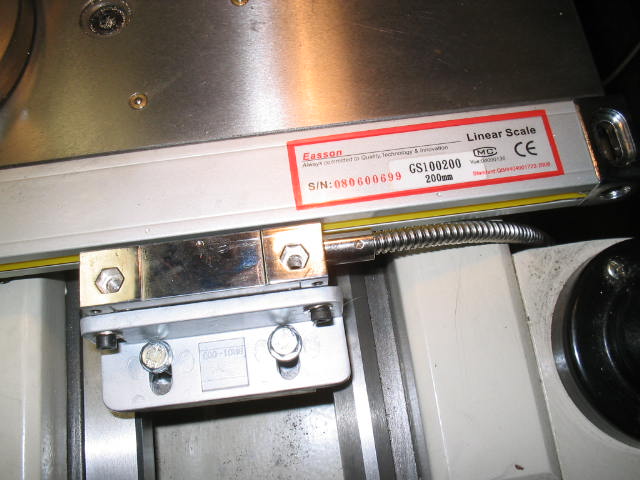
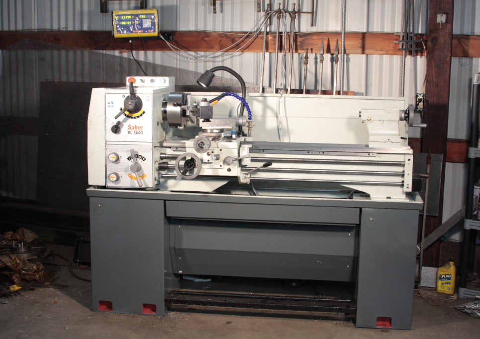
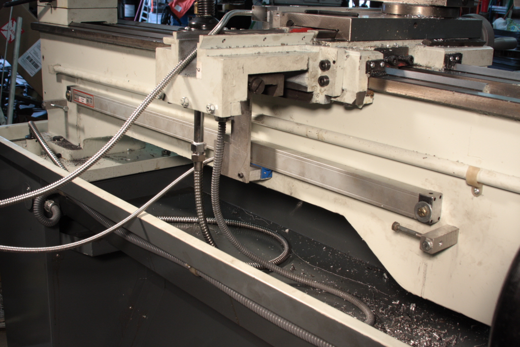
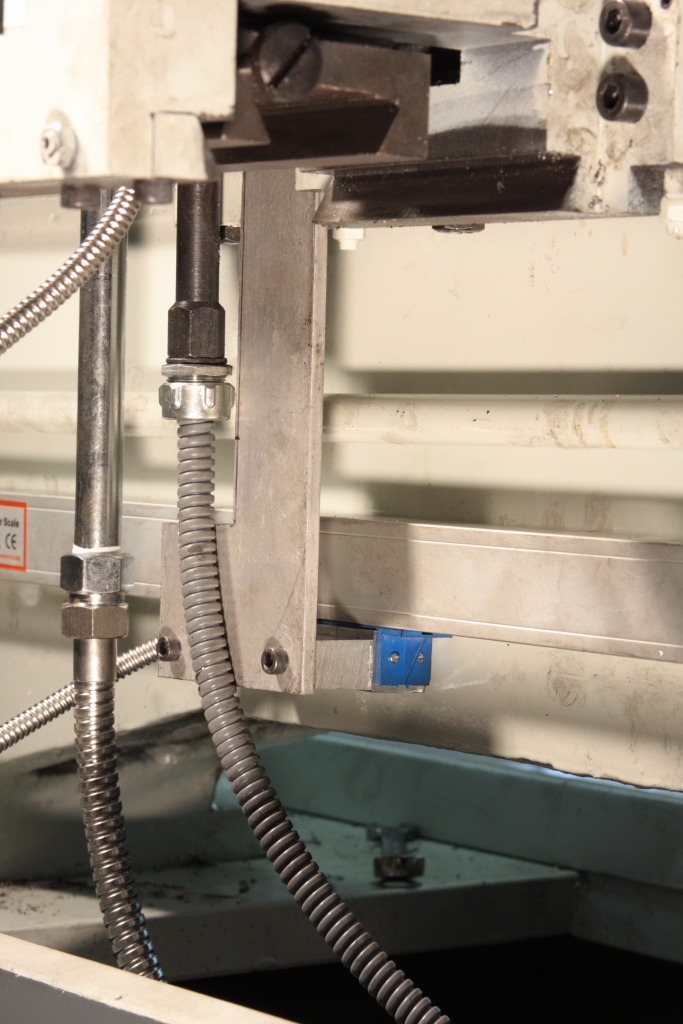
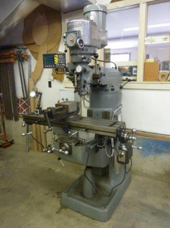
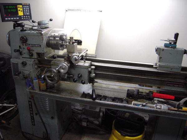
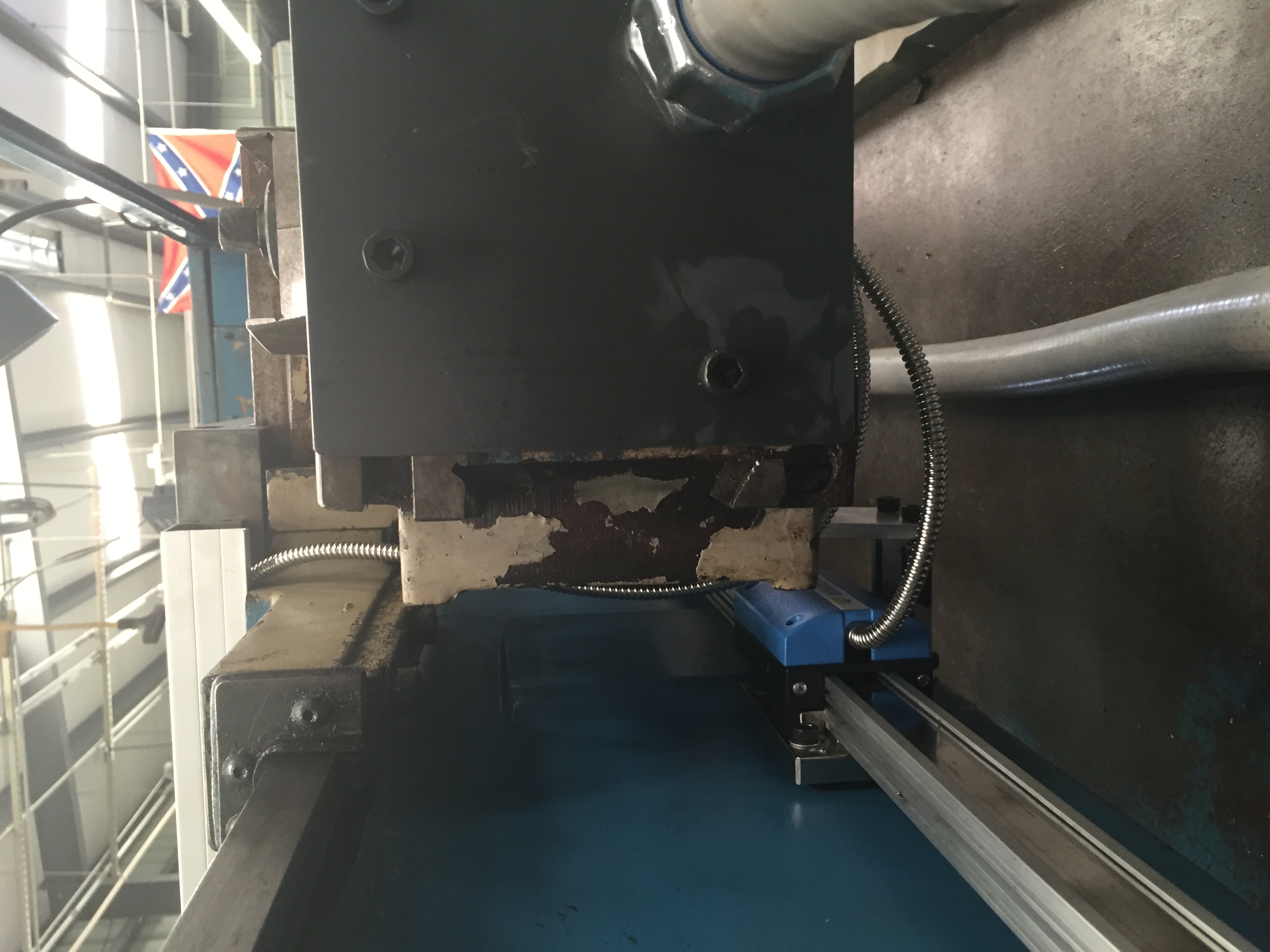
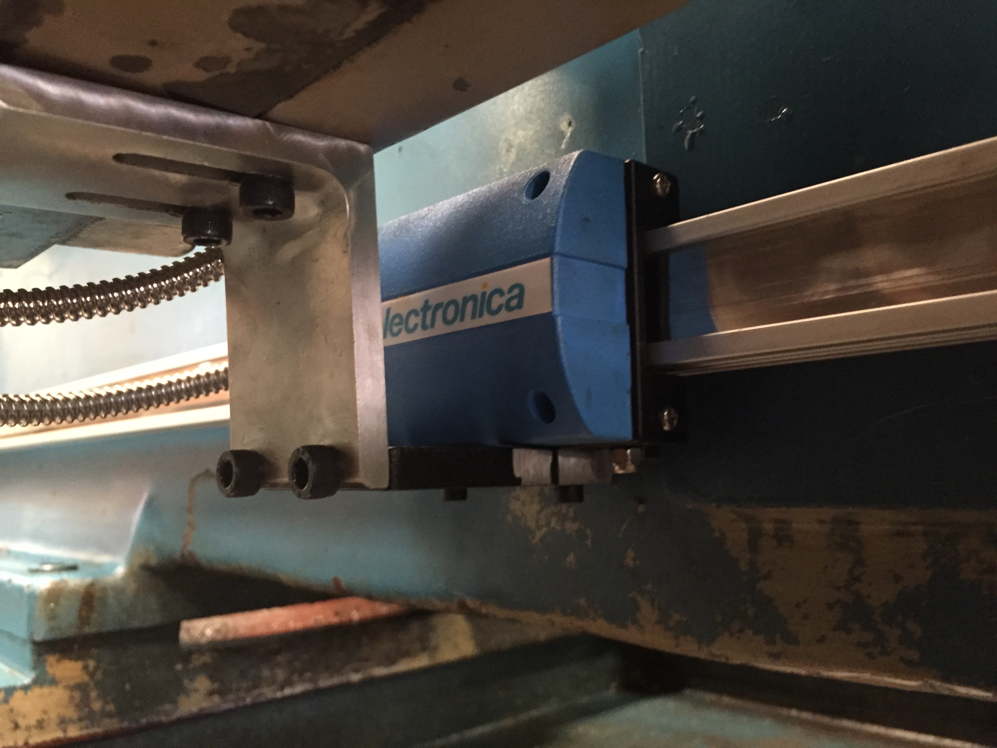
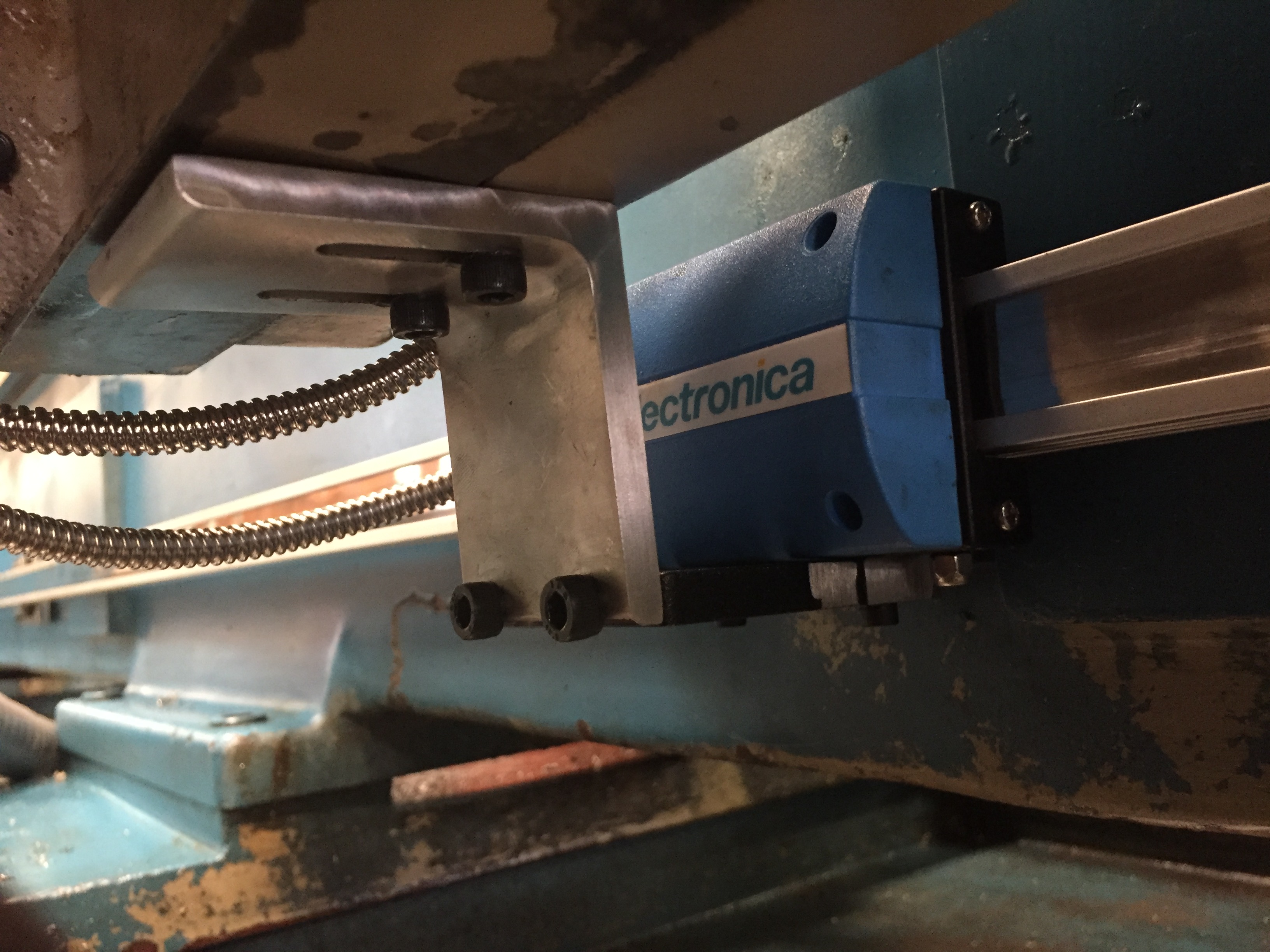
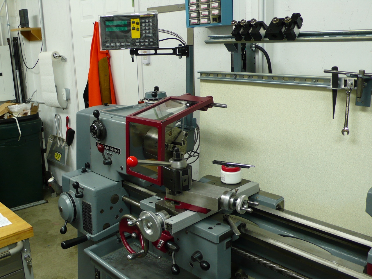
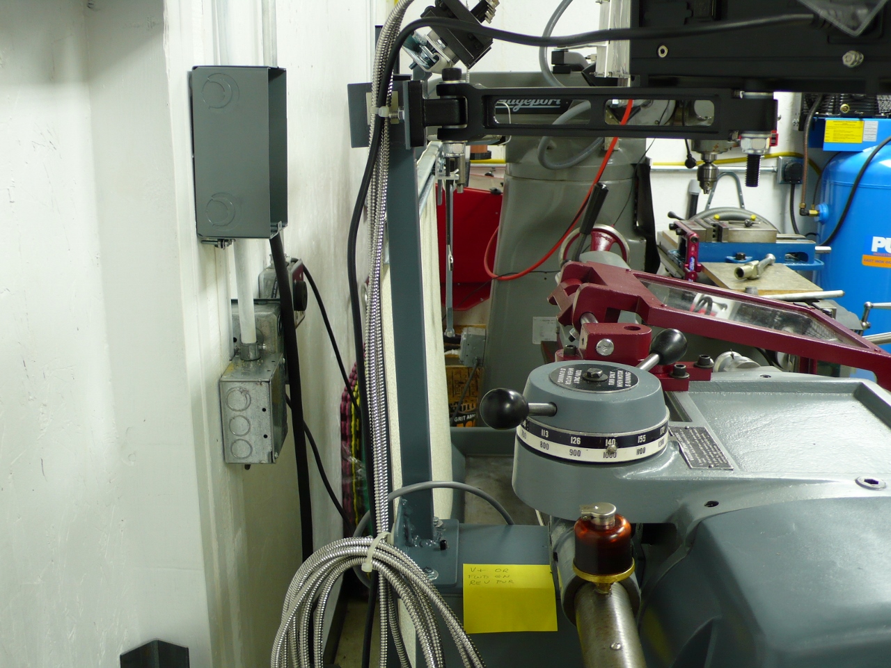
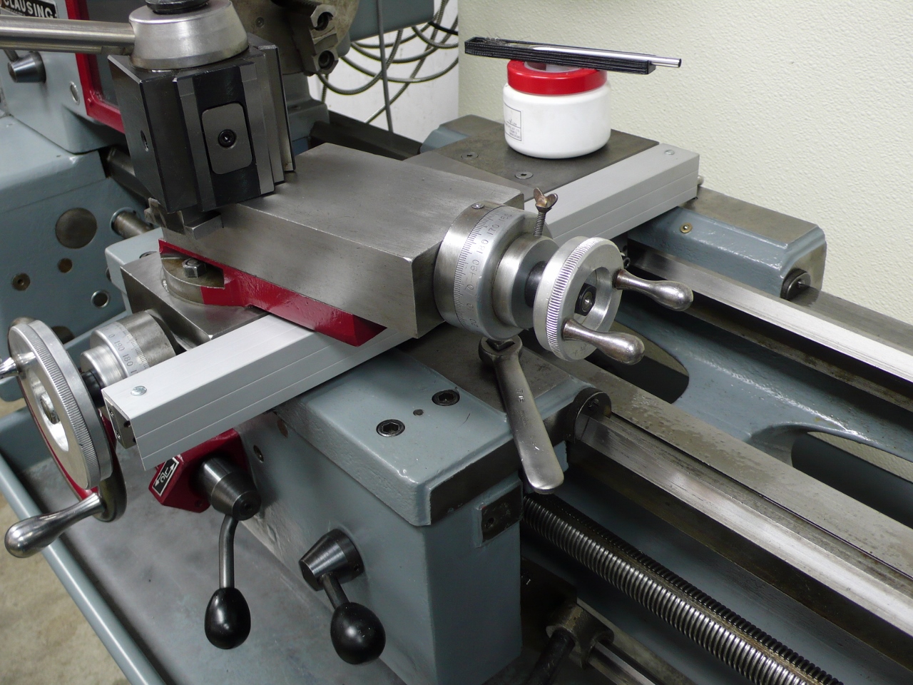
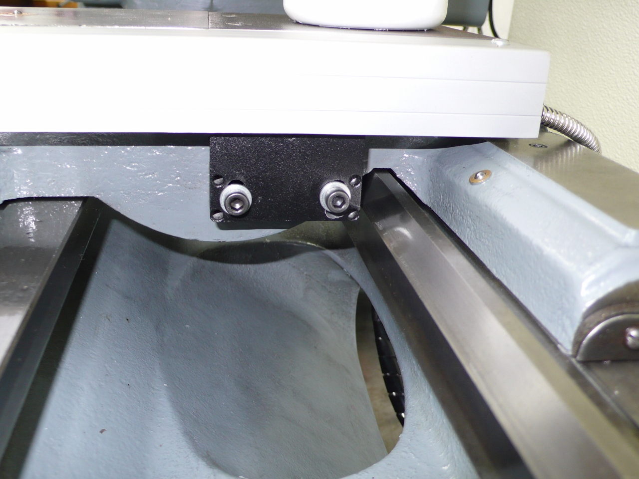
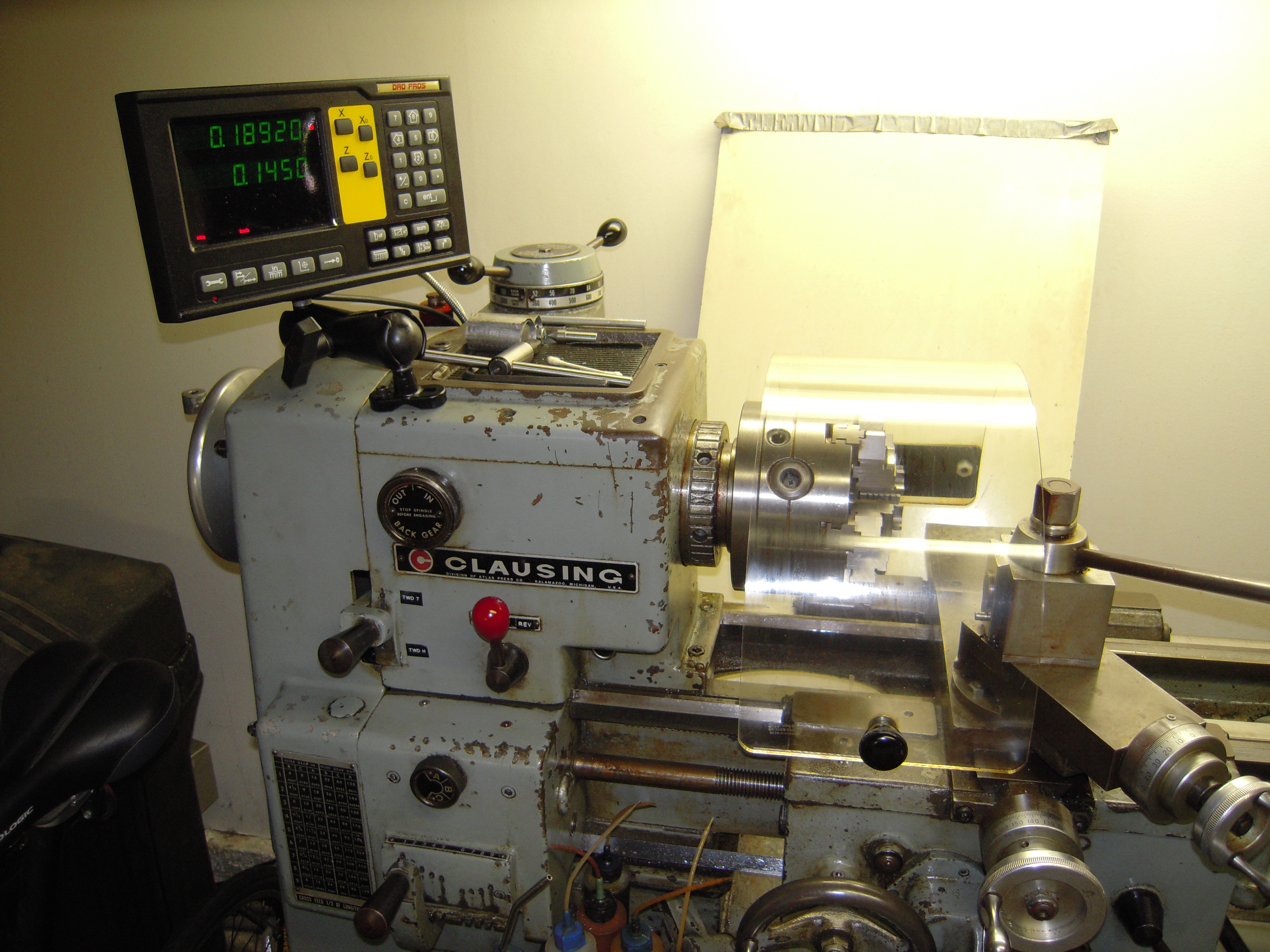
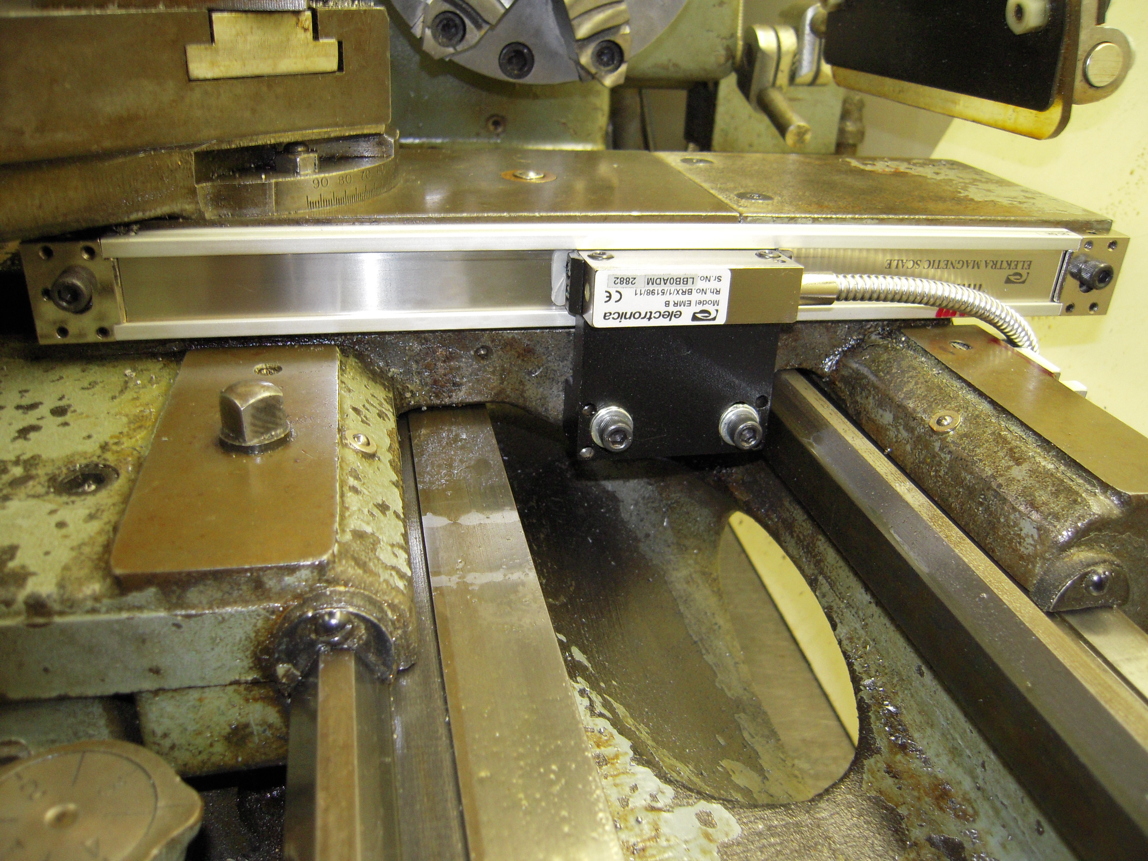
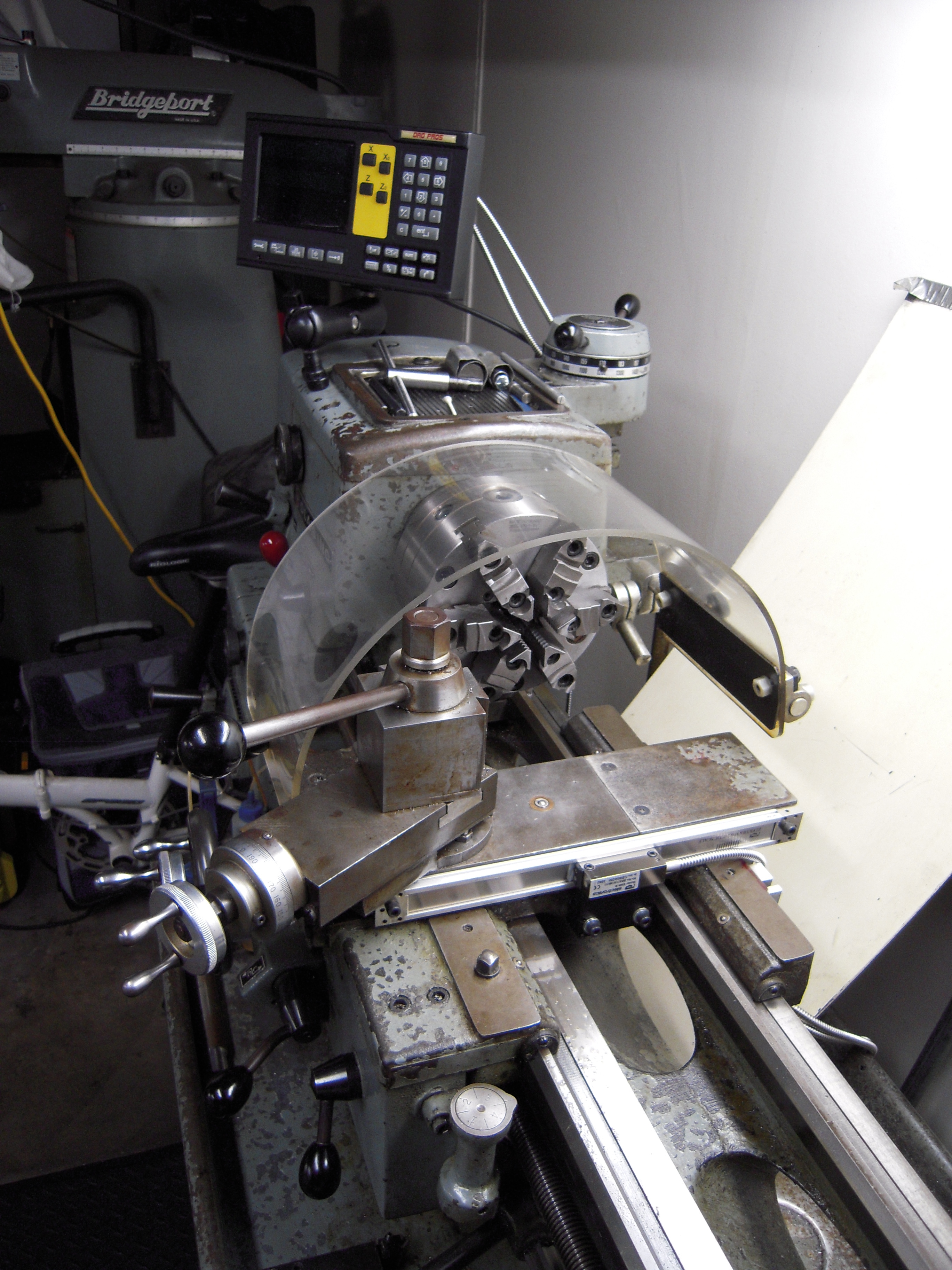
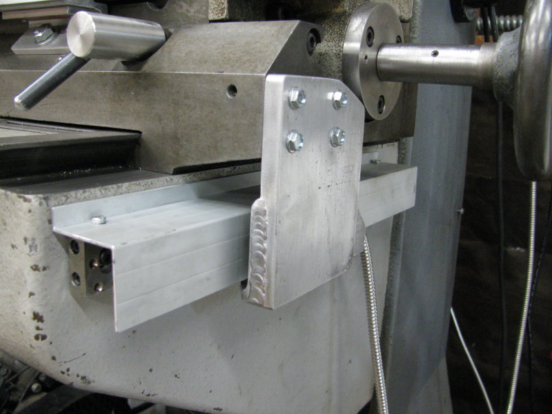
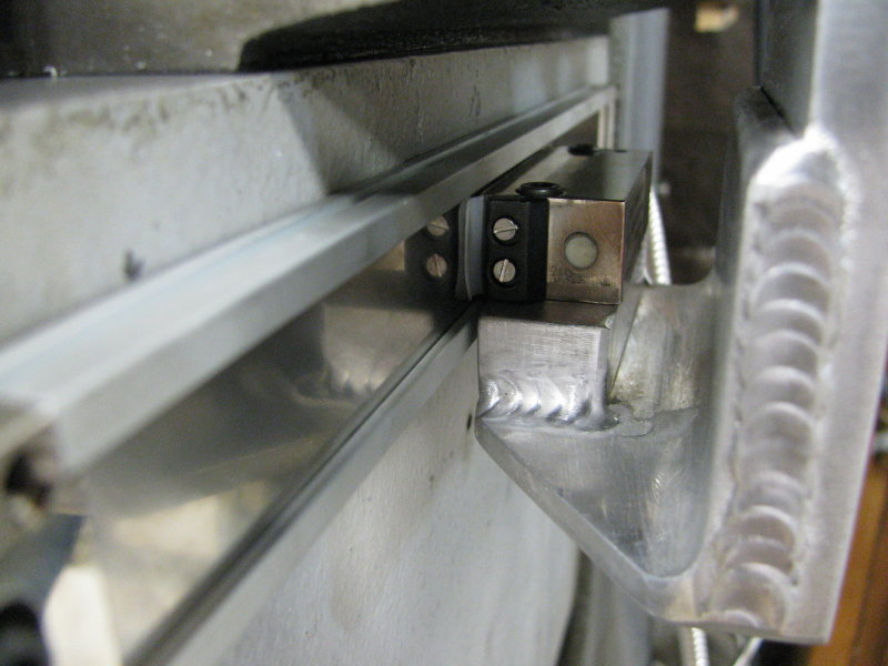
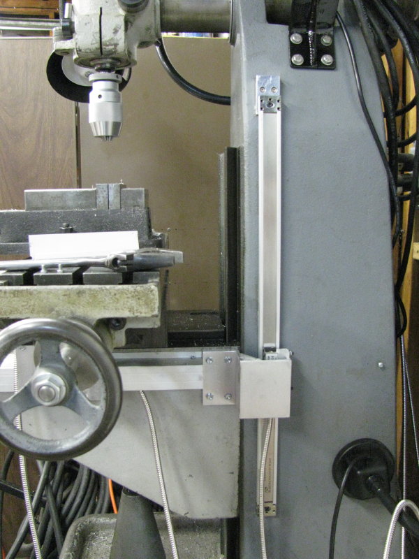
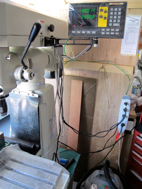
#26 - Courtesy
of T. Scholey with a DRO PROS Electronica Magnetic Scale Lathe Kit:
#27 - Courtesy
of L. Maraio with a Color LCD EL700 Magnetic Scale Mill Kit:
#28 - Courtesy
of P. Smith with a DRO PROS Electronica Magnetic Scale Mill Kit:
#29 - Courtesy
of R. Peters with a DRO PROS Electronica Magnetic Scale Lathe Kit:

#30 - Courtesy
of M. Hall with a DRO PROS Electronica Magnetic Scale Lathe Kit:
#31 - Courtesy
of J. Vietti with a DRO PROS Electronica Magnetic Scale Mill Kit:
#32 - Courtesy
of B. Summers with a DRO PROS Electronica Magnetic Scale Lathe Kit:
#33 - Courtesy
of D. Howe with a DRO PROS Electronica Magnetic Scale Lathe Kit:
#34 - Courtesy
of B. Shields with a DRO PROS Electronica Magnetic Scale Lathe Kit:
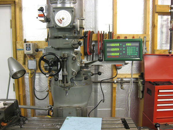
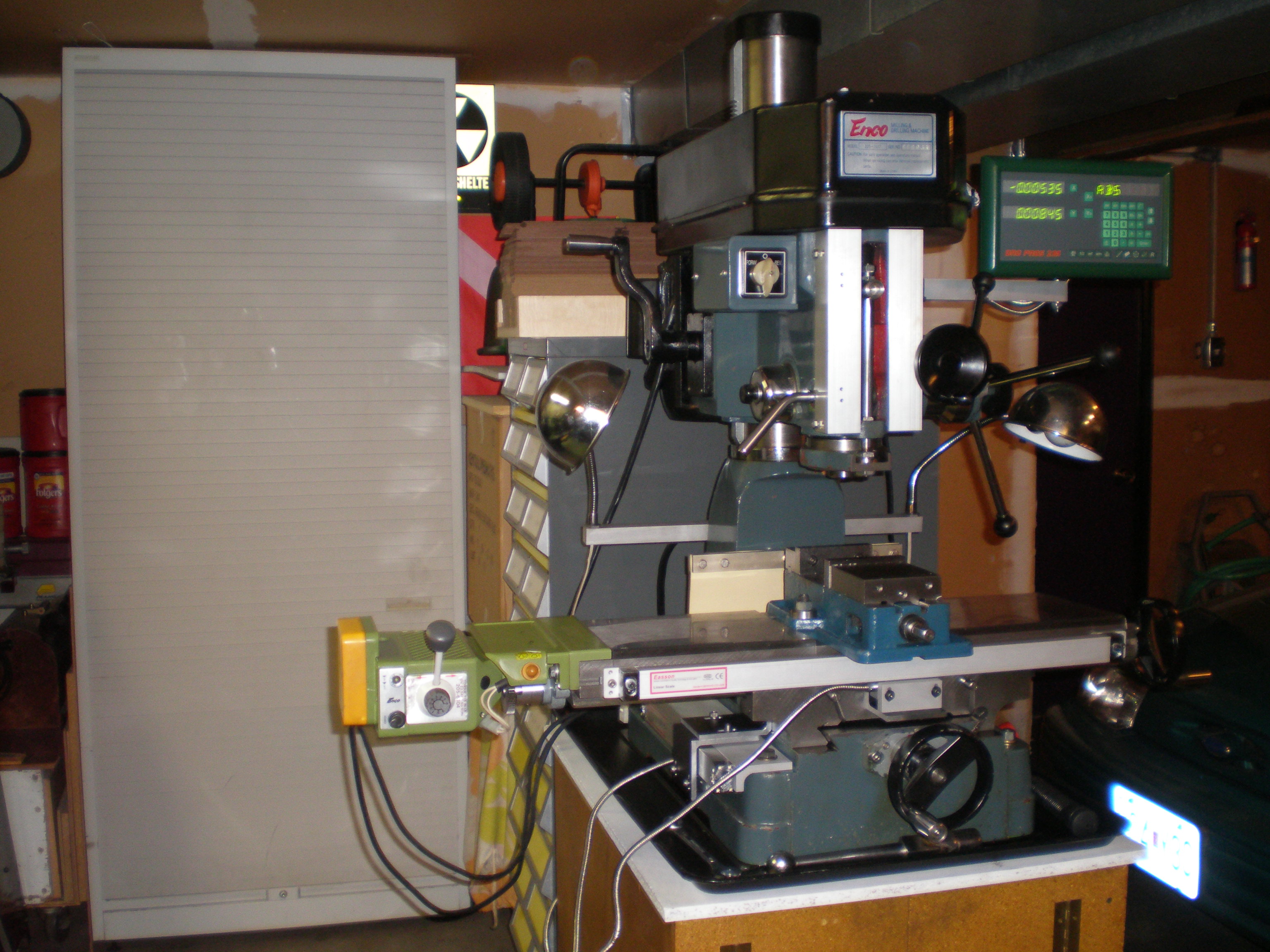
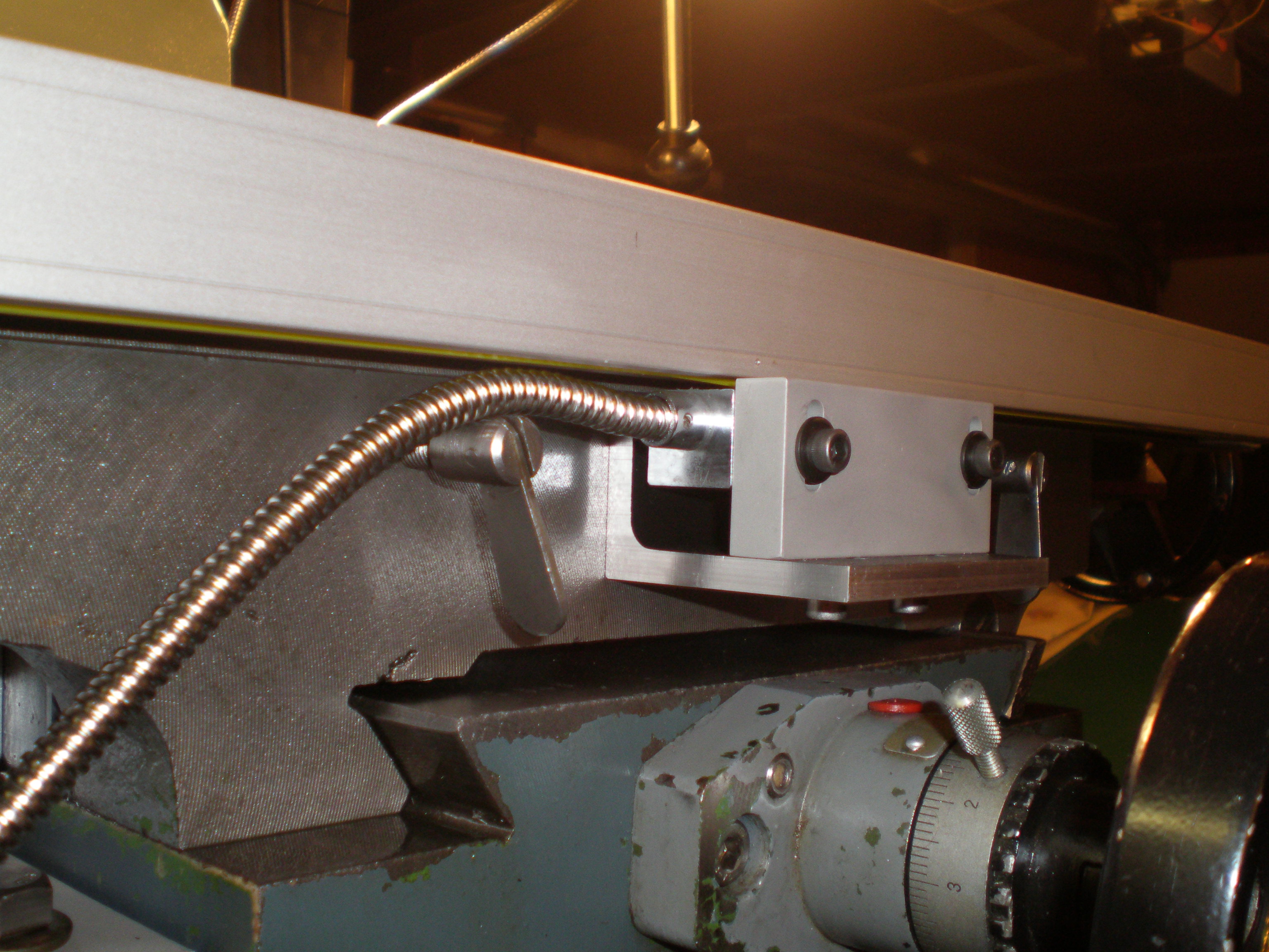
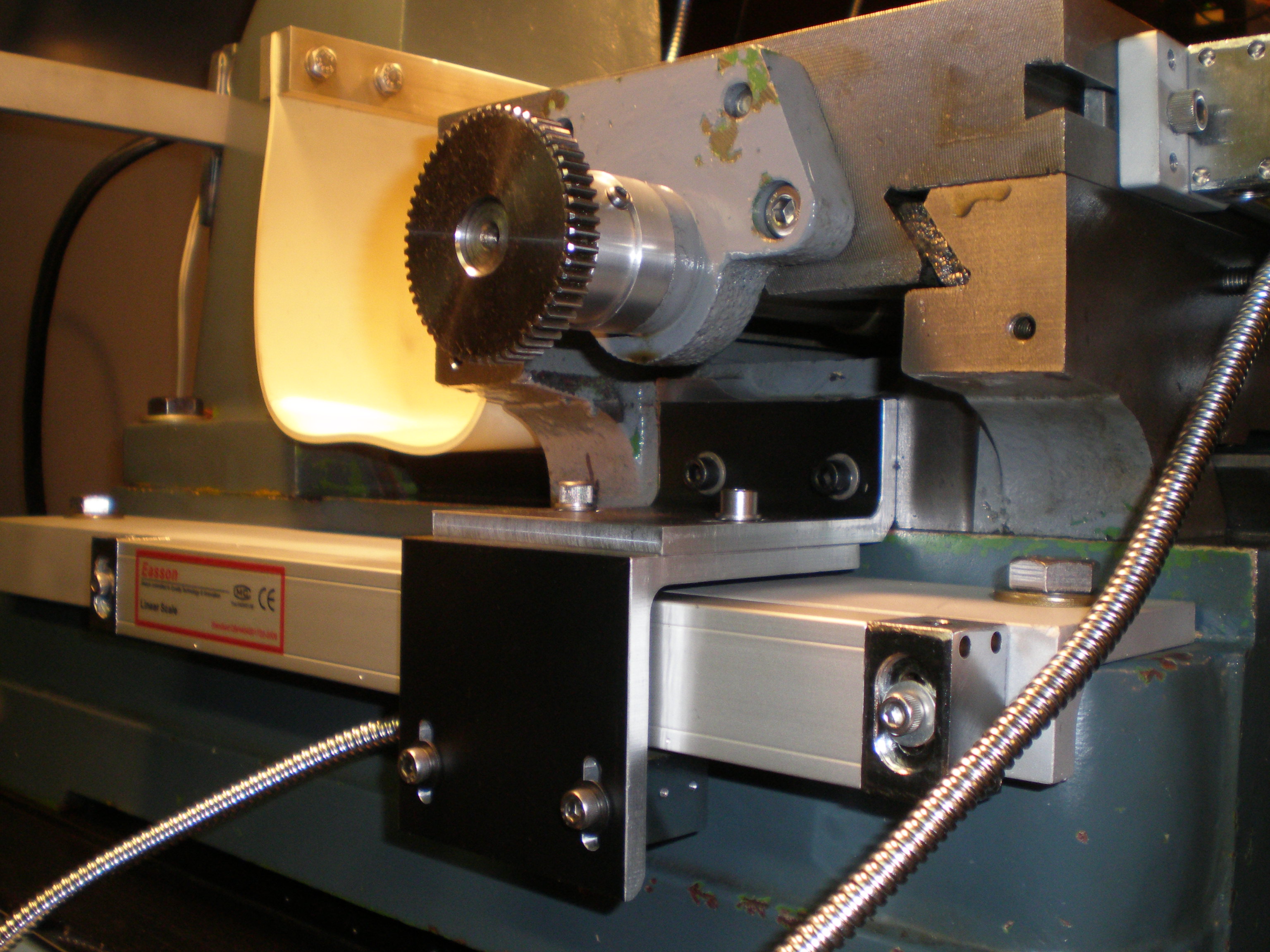
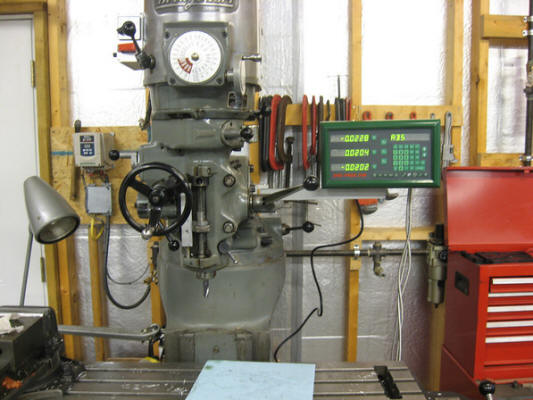
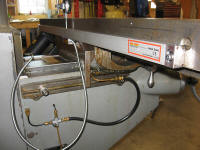
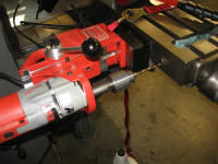
#35 - Courtesy
of K. Roon with a DRO PROS Electronica Magnetic Scale Mill Kit:
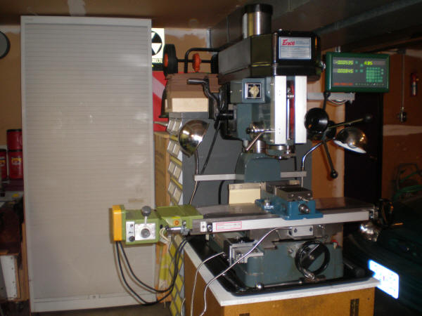
#36 - Courtesy
of W. Mitzen with a DRO PROS Electronica Magnetic Scale Mill Kit:

#37 - Courtesy
of P. Howell with a DRO PROS Electronica Magnetic Scale Mill Kit:
#38 - Courtesy
of R. Hardwick with a DRO PROS Electronica Magnetic Scale Mill Kit:
#39 - Courtesy
of M. Roberts with an Electronica Magnetic Scale 300 "Universal" Kit:
#40 - Courtesy
of S. Gooselaw with a DRO PROS Electronica Magnetic Scale Mill Kit:
#41 - Courtesy
of R. Munoz with a DRO PROS Electronica Magnetic Scale Mill Kit:
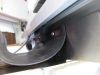 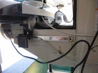 
#42 - Courtesy
of T. Doran with a DRO PROS Electronica Magnetic Scale Mill Kit:
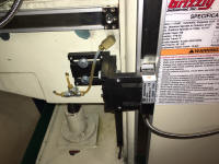
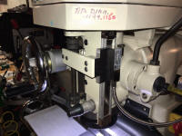
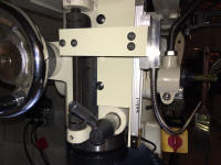
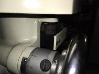
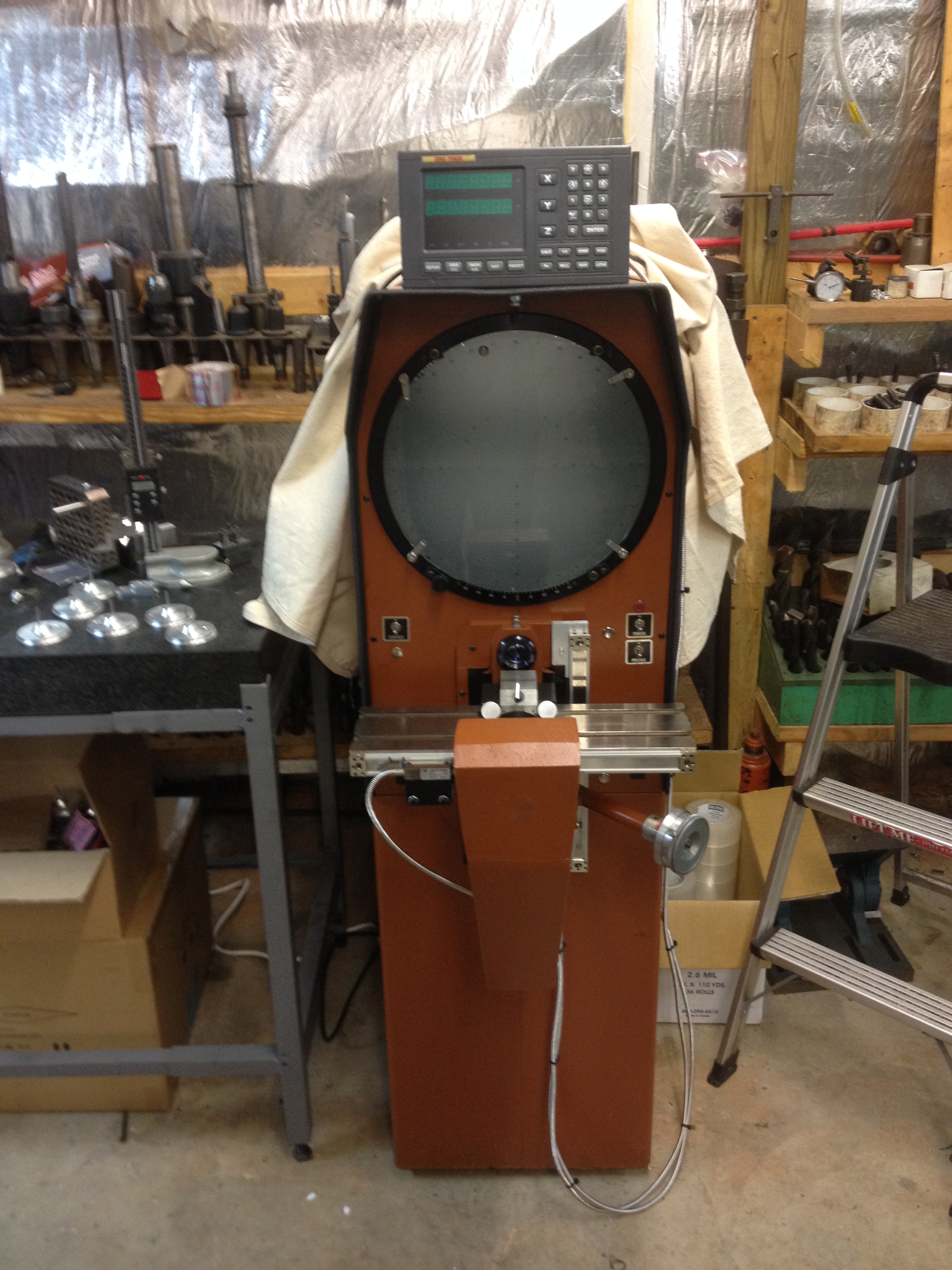
#43 - Courtesy
of R. Lyn with a DRO PROS Electronica Magnetic Scale Kit:
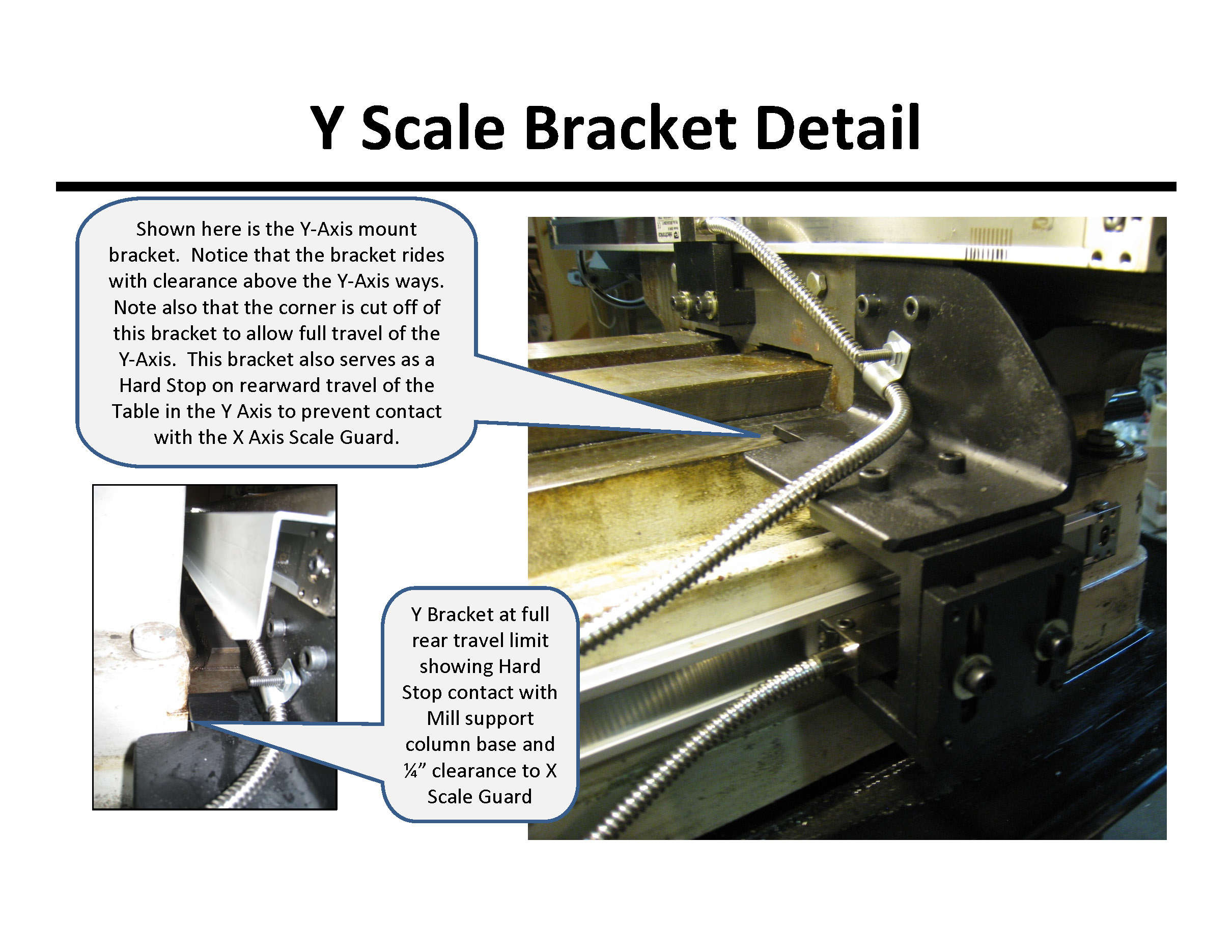
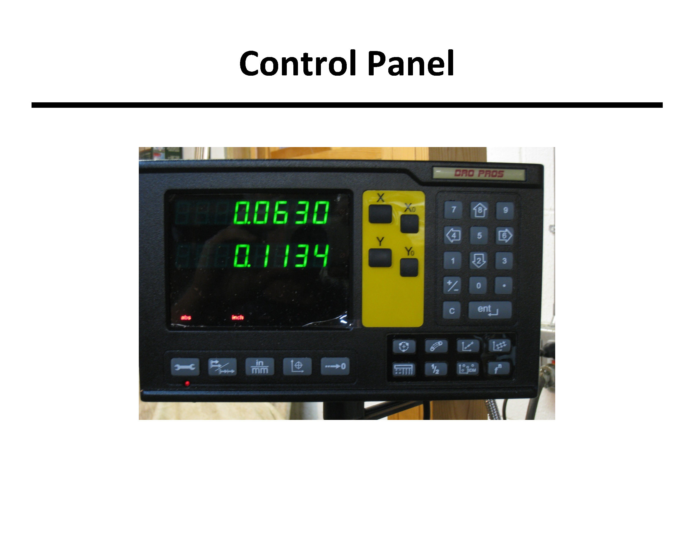
(custom mounted to an optical comparator)

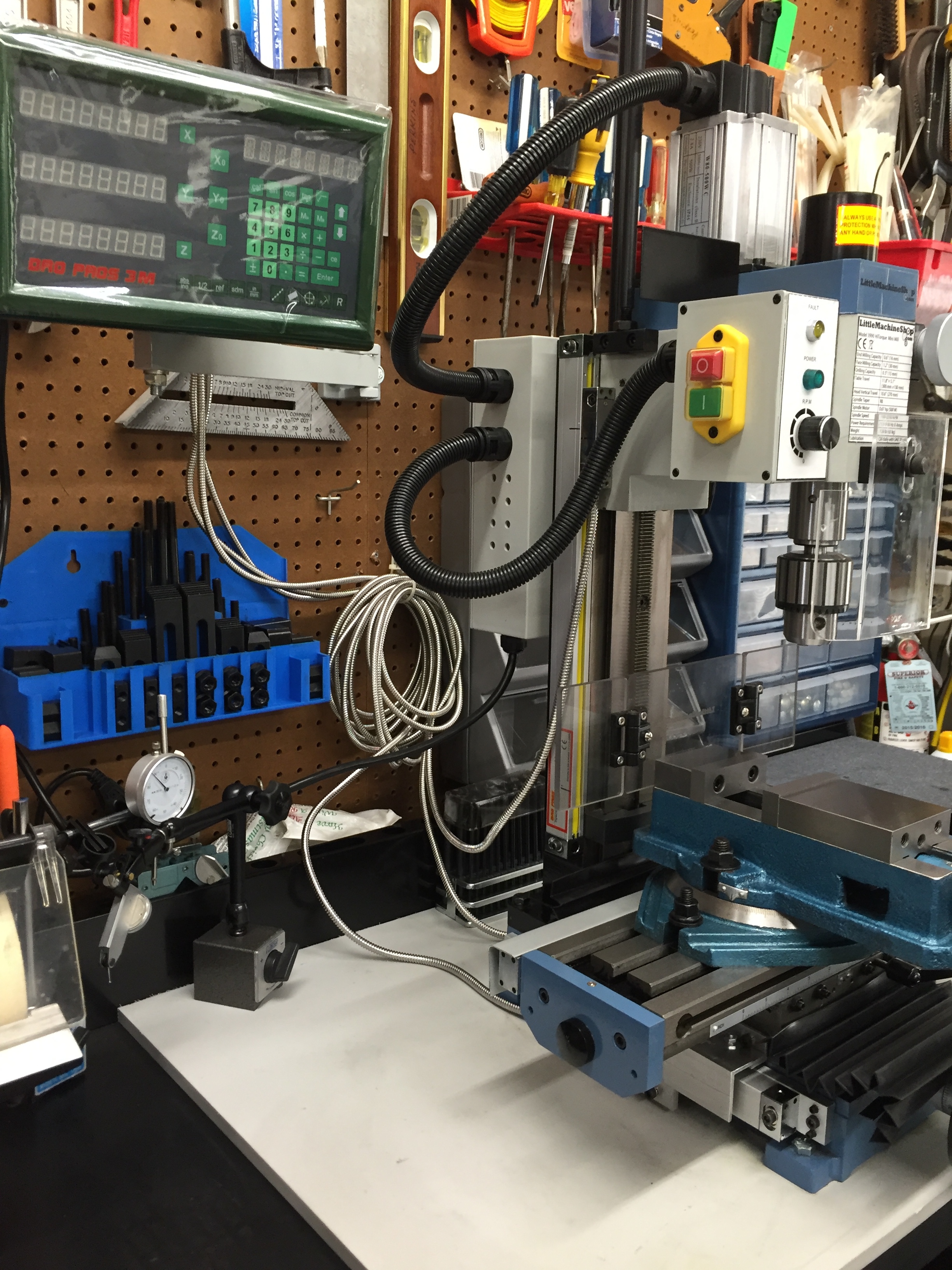
#44 - Courtesy
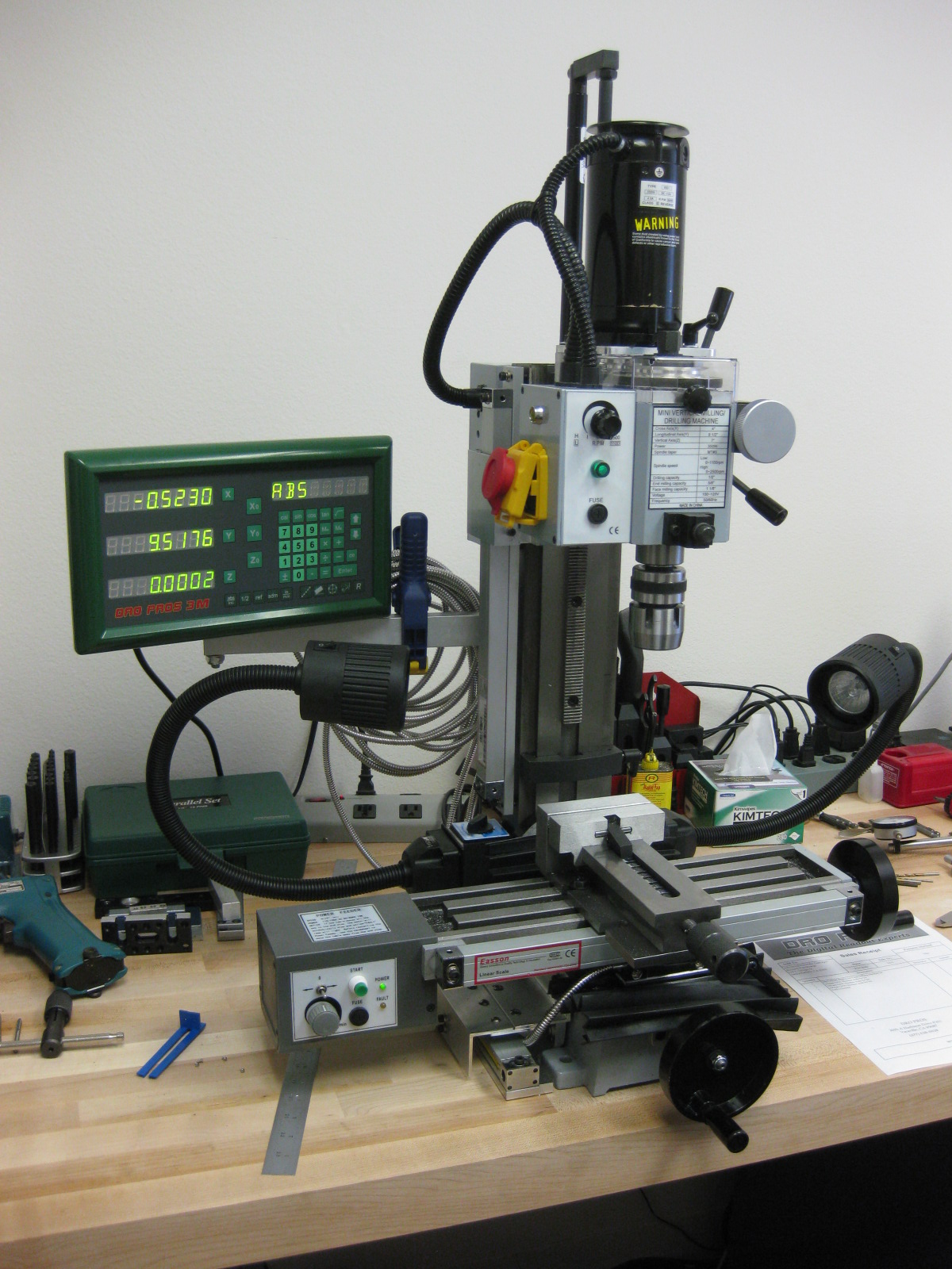
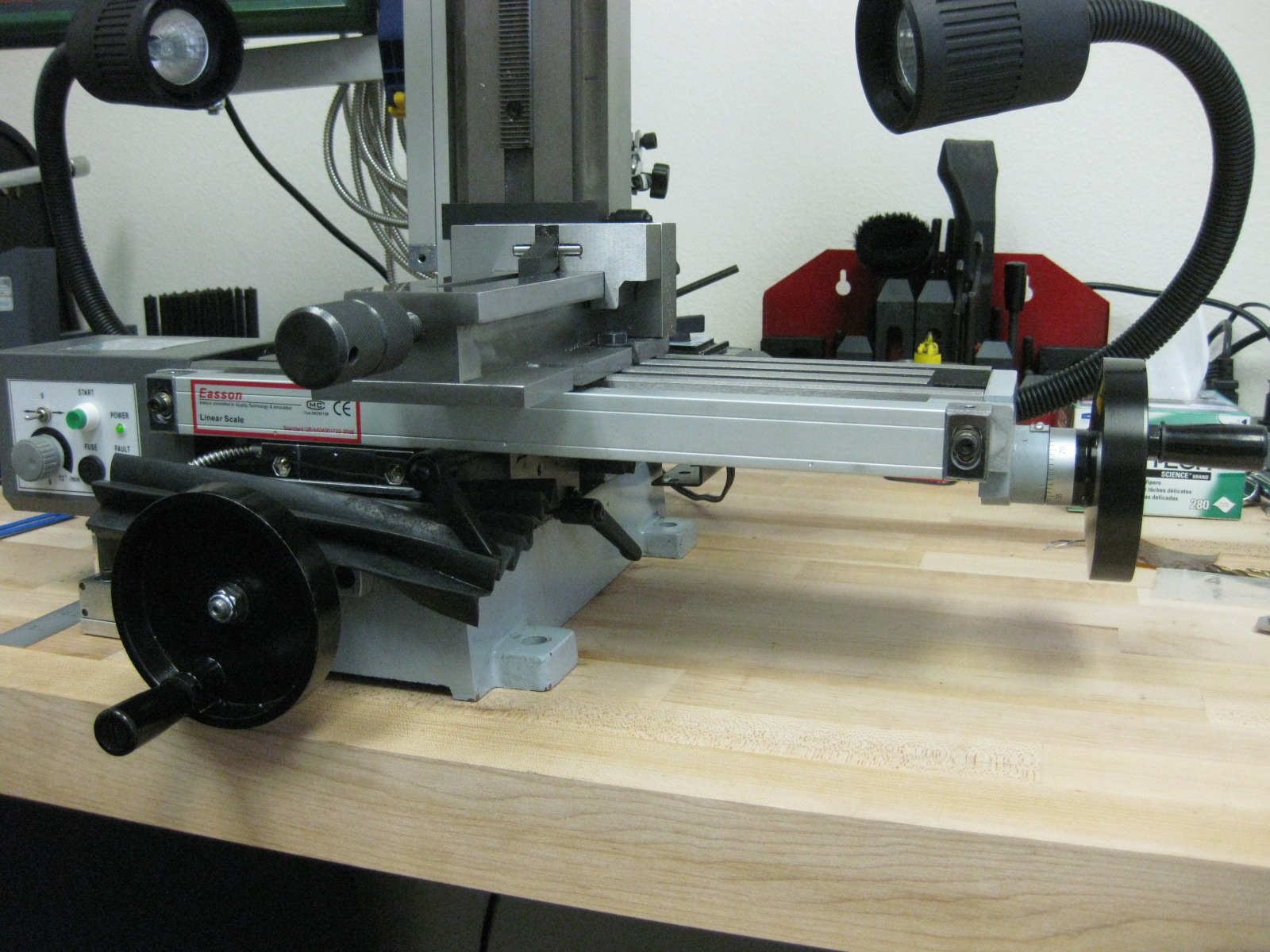
of J. Perkins with a DRO PROS 3M three axis glass scale Mill Kit:
#45 - Courtesy
of Wil with a DRO PROS 3M three axis glass scale Mill Kit:

#46 - Courtesy
of M. Niadna with a DRO PROS Glass Scale Lathe Kit:
#47 - Courtesy
of Unknown with a DRO PROS 3M three axis glass scale Mill Kit:
#48 - Courtesy
of H. Kratz with a DRO PROS 3M three axis glass scale Mill Kit:
  %20(2).jpg)
#49 - Courtesy
of G. Young with a DRO PROS 3M three axis glass scale Mill Kit:
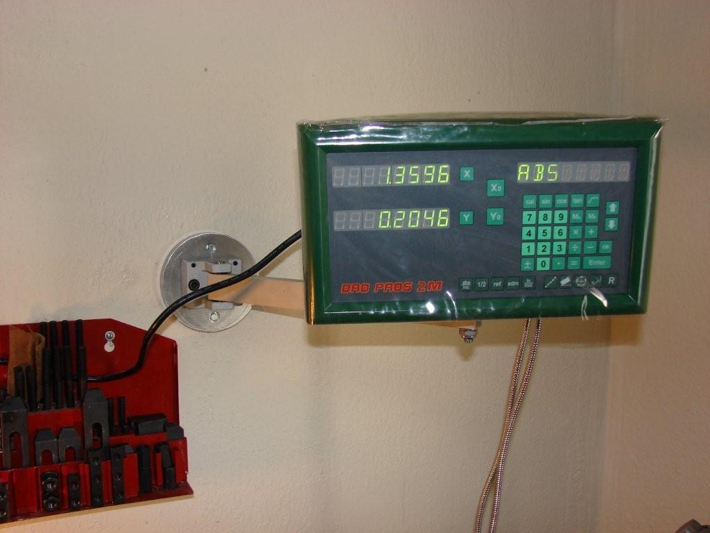
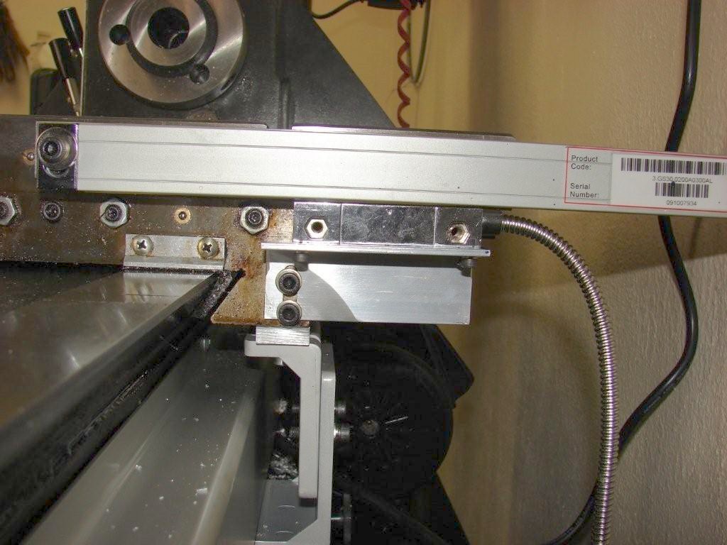
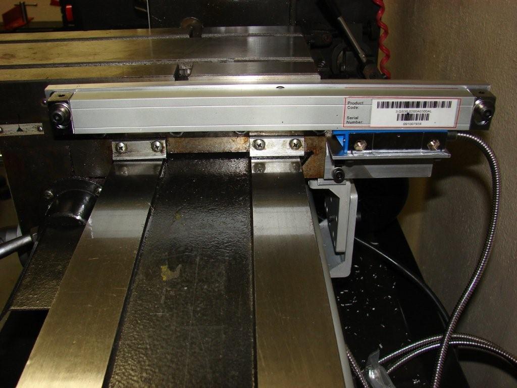
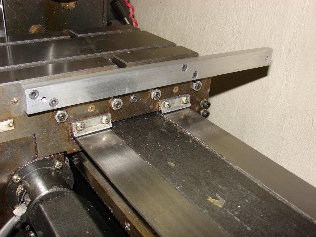
#50 - Courtesy
of R. Herold with a DRO PROS 2M two axis glass scale Mill Kit:
#51 - Courtesy
of R. Hartshorne with a DRO PROS 3M three axis glass scale Mill Kit:
#52 - Courtesy
of J. Guest with a DRO PROS 3M three axis glass scale Mill Kit:
#53 - Courtesy
of M. Crego with a DRO PROS 3M three axis glass scale Mill Kit:

#54 - Courtesy
of Dave with a DRO PROS 3M three axis glass scale Mill Kit:
#55 - Courtesy
of Bjorn H. with a DRO PROS 3M three axis glass scale Mill Kit:
  
#56 - Courtesy
of K. Byrd with a DRO PROS 3M three axis glass scale Mill Kit:
#57 - Courtesy
of John B. with a DRO PROS 2M two axis glass scale Mill Kit:
 
Here is a link
to his comments:
John B's
Comments
#58 - Courtesy
of J. Gillies with a DRO PROS 3M three axis glass scale Mill Kit

#59 - Courtesy of
J. Iseli with a DRO PROS 2M two axis glass scale Mill Kit:
#60 - Courtesy of
B. Martin with a DRO PROS 3M three axis glass scale Mill Kit:
#61 - Courtesy
of P. Thompson with a DRO PROS 3M three axis glass scale Mill Kit:
#62 - Courtesy
of T. Ancell with an Easson ES10-3M5 three axis glass scale Mill Kit:
#63 - Courtesy of
R. Fenichel detailing how to mount a Z glass scale on a Sieg SX3:
Here is the link to
his detailed instructions:
SX3 Z
Scale Install
#64 - Courtesy
of J. Hicks with an Easson ES10-3M5 three axis glass scale Mill Kit:

#65 - Courtesy
of H. Noble with an Easson ES10-3M5 three axis glass scale Mill Kit:
#66 -
Courtesy of W. Pfeiffer with an Easson ES10-3M5 three axis
glass scale
Mill Kit:

#67 - Courtesy of
(unknown) with an Easson ES10-3M5 three axis glass scale Mill Kit:
#68 - Courtesy of R.
Partridge with an Easson ES10-2M5 two axis glass scale Mill Kit:

#69 - Courtesy of B. Ohlemann with an Easson ES10-2M5 two axis glass scale Mill Kit:
#70 - Courtesy of D.
Collins with an Easson ES10-2M5 two axis glass scale Mill Kit:
#71 - Courtesy
of V. Esplin with a DRO PROS 2L two axis glass scale Lathe Kit:
#72 - Courtesy
of M. McDevitt with a DRO PROS 2L two axis glass scale Lathe Kit:

#73 - Courtesy of
D. Roth with a DRO PROS 2L two axis glass scale Lathe Kit:
#74 - Courtesy of
A. Wilson with a DRO PROS 2L two axis glass scale Lathe Kit:
#75 - Courtesy
of G. Inglehart with an Easson ES10-3L5 three axis glass scale Lathe
Kit:
#76 - Courtesy
of R. Suttle with an Easson ES10-2L5 two axis glass scale Lathe Kit:
#77 - Courtesy
of J. Dolde with an Easson ES10-2L5 two axis glass scale Lathe Kit:
  
#78 - Courtesy of K.
Coker with an Easson ES10-2L5 two axis glass scale Lathe Kit:
#79 - Courtesy of R. Pleas
with an Easson ES10-2L5 two axis glass scale Lathe Kit:
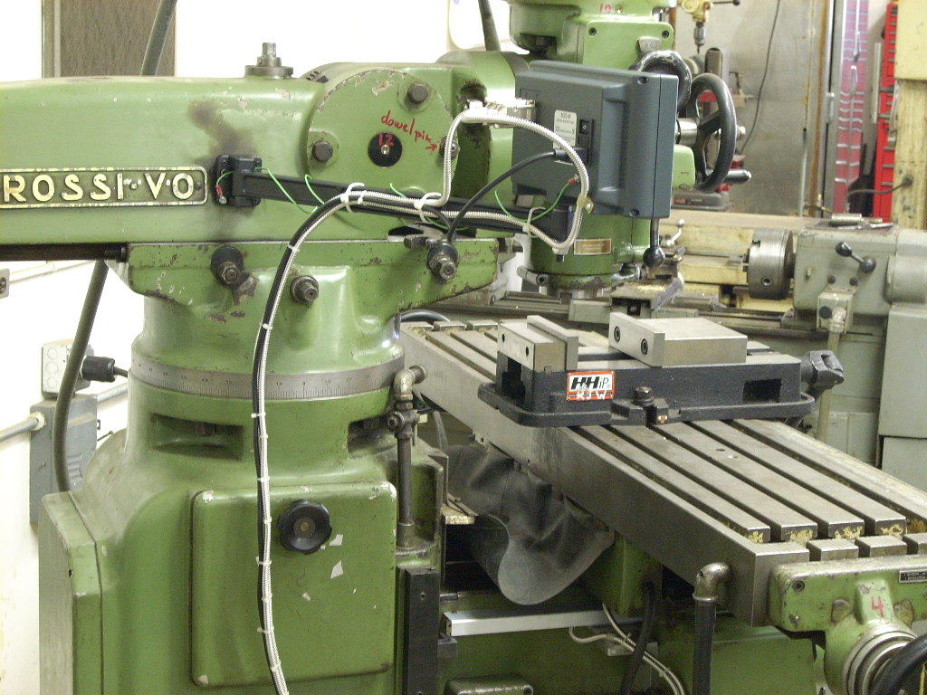
#80 - Courtesy of J.
Holmgren with a Newall M20 two axis magnetic scale Mill Kit:
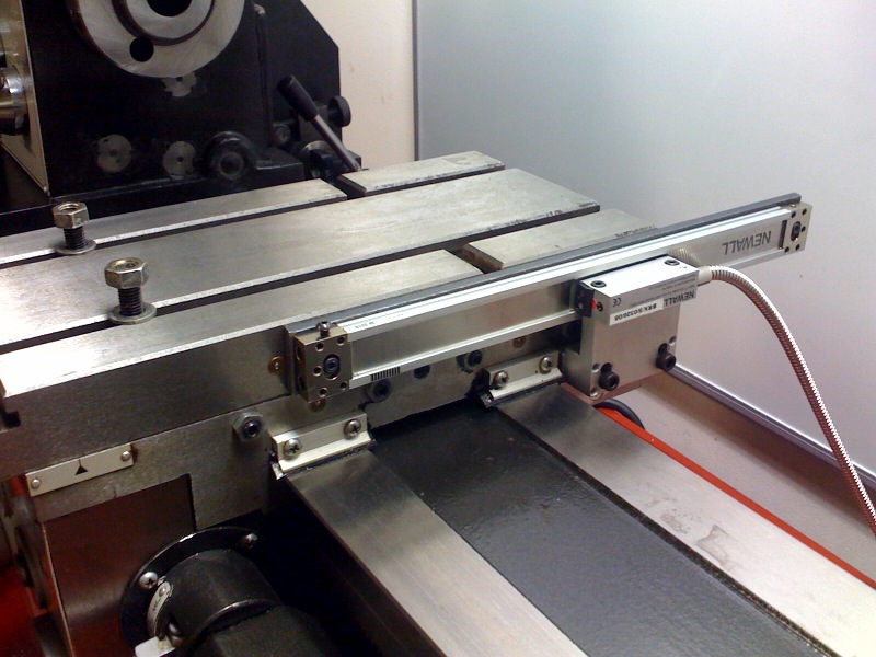
#81 - Courtesy
of S. Chase with a Newall M20 two axis magnetic scale Lathe Kit:
  
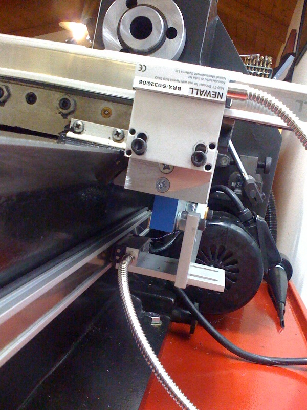
#82 - Courtesy
of R. Wells with a Newall M20 two axis magnetic scale Mill Kit:
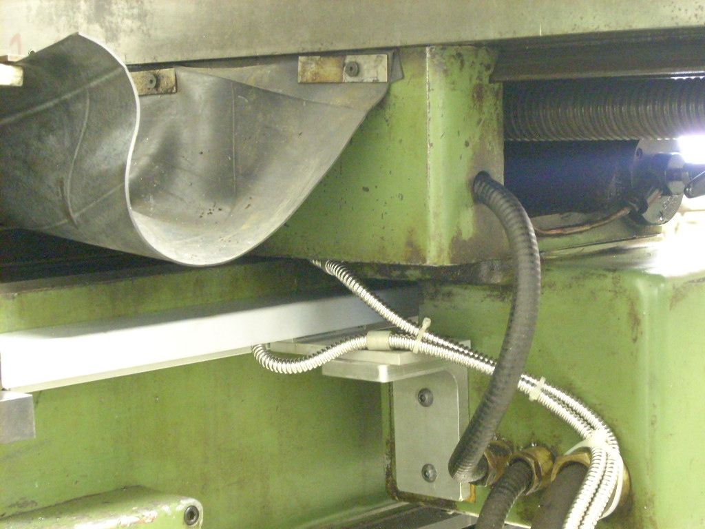
#83 -
Courtesy of R. Snyder with a Newall M20 two axis magnetic scale Lathe
Kit:
#84 - Courtesy of D.
Hall with a Fagor Innova two axis glass scale Lathe Kit:

Hints and
Techniques from our Customers
DRO KIT
Installation - Notes, Warnings and Cautions
The Readhead
- What the readhead looks like
The Threaded Holes
- Size and tap sizes for mounting the scale
Nuts & Bolts
- Specifications of fasteners included with our kits
Prepping the Scale -
How to protect the scale so
the readhead doesn't run into the end
Dragging the Scale
- How to ensure the readhead doesn't drag the inside of the scale
Do
I have to center the scale on the table? - Tips on where to mount the
scales
Bracket Alignment -
How to line the mill kit
brackets up with the holes
Mill Installation
-
Excerpts from the Mill
Installation Booklet
Click HERE to read how to
initialize 1 micron scales on the DRO PROS 2L Lathe Kit
Click HERE to read how to
initialize 1 micron scales on the DRO PROS 2M Milling Machine Kit
Click HERE to read how to
initialize 1 micron scales on the DRO PROS 3M Milling Machine Kit
The "Blue
Strip"- Between the scale and the reader head there is a blue strip
which helps to maintain the correct distance between the reader head and
the scale for installation purposes. This should be removed after
installation.
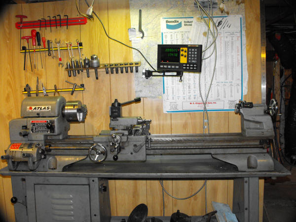
Hints and
Techniques from our Customers
Sometimes it's best to let
your customers do the talking
(Please click on Mikes'
letter to the right for the full install story and photos).
Look at what Mike Grey of
AWMS Inc. had to say about his DRO PROS Installation:

18 Jul 2010
DRO PROS,
You were most
helpful when I was looking to purchase a DRO for my lathe - so
thought I would drop you a line and let you know how things turned out as well
as offer some other information.
I suggest you
consider adding a spot on your web site that shows customer installs of your
products on various machines. The way others solve the problems of
installation would be helpful for ALL users. Particularly, if the
installation is on a similar machine. Should you choose to do so, here is
my contribution.
Sincerely,
Mike Gray
DRO KIT
Installation - Notes, Warnings and Cautions
Between the
scale and the reader head there is a blue strip which helps to maintain
the correct distance between the reader head and the scale for
installation purposes. This should be removed after installation.
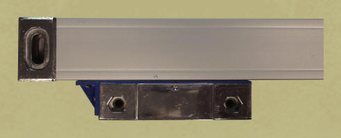
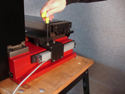
Note: To give the
best
protection, the scale should be mounted with the yellow rubber seals (lips)
facing down. Note that this is not always possible. The scale performs equally
well mounted in any direction. It's just that optimally, the best protection is
afforded with the opening facing down or away from the cutting tool.
The travel length of the
glass grating scale must be longer than the maximum travel of the machine, there
should be at least 10mm clearance (approximately 1/2") between the ends of the
glass scale and the maximum travel of the machine as shown in the following
figure:
It is very
important that the scale body be aligned parallel to the travel of the
machine slide. For scale travel less than 950mm, the maximum parallel
error between the scale and the machine slide must be less than 0.15mm.
For scales longer than 950mm, the maximum alignment parallelism error
must be less that 0.1mm:
The
clearance between the reader head and scale body must be kept between
0.8mm - 1.5mm.
If a dial
indicator is used to align the scale, it is important to ensure that the
angle between the dial indicator lever tip and the surface measured is
less than 3 degrees to avoid a cosine measurement error. lf a vertical
dial indicator is used as per the following figures shown, it is
important to ensure that the dial indicator is perpendicular to the
measured surface to avoid any error:
The opening of the
scale must not be installed as to be directly exposed to swarf, oil,
water, dust or other foreign products. The provided protectant covers
should be installed.
The scales should be
installed on a level, machined surface.
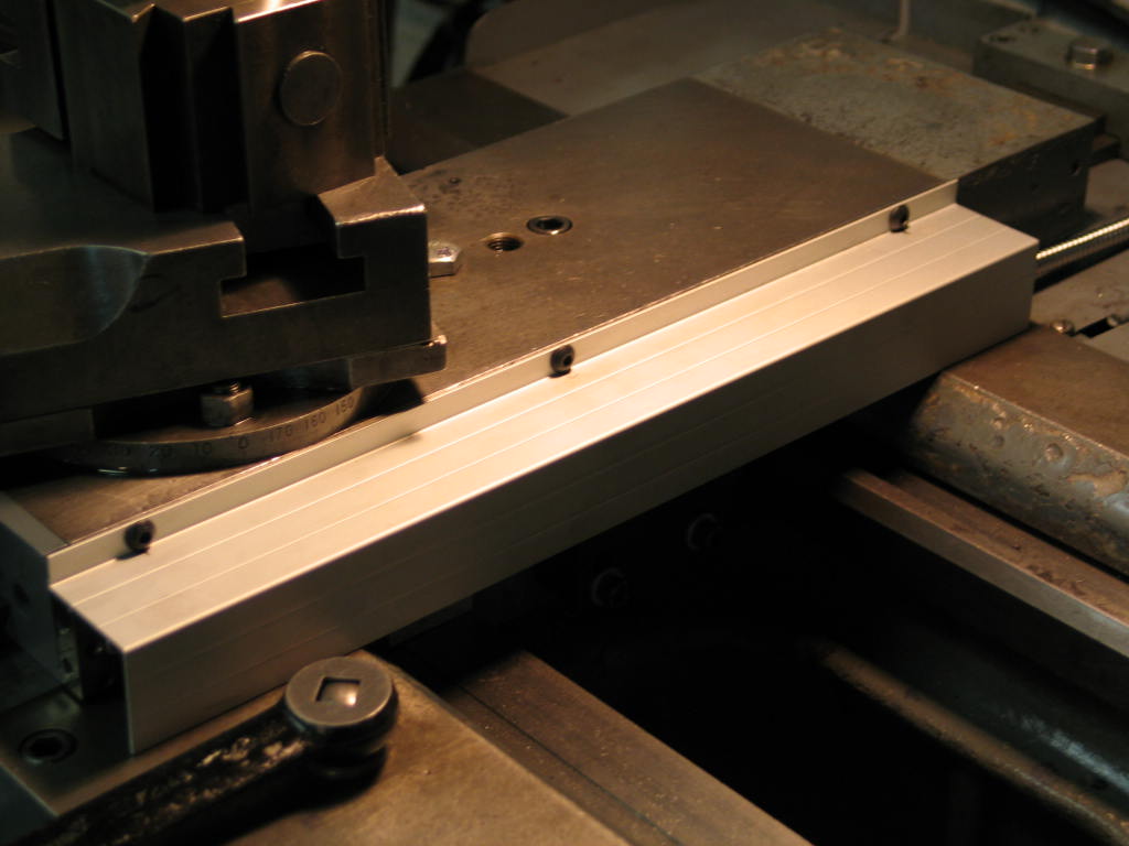
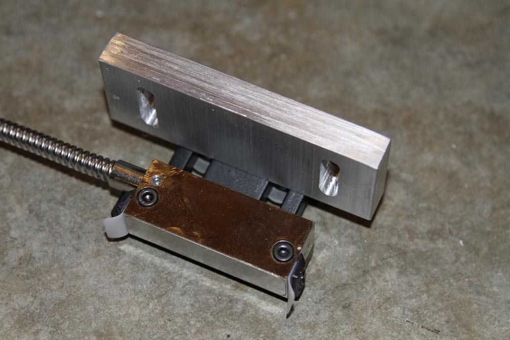
In cases where
machined flat surfaces are not available, an installation block or strip
should be used to provide a flat datum for the installation:
There must be a
clearance of at least 3.0mm between the scale and the scale cover:
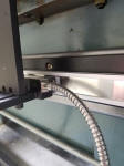
All cables should
be fixed, but still allow for the maximum amount of machine travel.
If
fitting the Z axis, the scale should be installed on the side of the
column, ensuring that the open side of the scale is away from direct
swarf and coolant. The bracket is mounted on the knee, and should wrap
around the scale to allow for the cover to protect the scale.
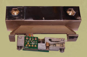
DRO KIT
Installation - Parts and Pieces
The first thing we
recommend is to get familiar with the scales. First, let's go over the parts of
a scale. The main housing is referred to as the scale body. The reader or
readhead is actually inside of the scale, and is self-guided by five ball
bearings along tracks inside the housing. The outside piece is the "trolley" and
simply pushes and pulls the readhead along the length of the scale body. The
"joint" between the trolley and the readhead is a metal arm which terminates at
the readhead in a kind of ball-and-socket joint. The point of this all is that
the readhead is self-aligning, meaning that the outside trolley does not
need to be in perfect parallel alignment with the scale body.
The Readhead
When looking at a scale
for the first time, the first thing that catches most peoples eyes is the 'blue
plastic piece' between the trolley and the scale body. It is intended to keep
the readhead from moving during shipping, but also serves as an excellent tool
for determining the offset or distance the trolley should be mounted away from
the scale body. At the end of the day, it will be in the trash, but for now,
don't discard it.
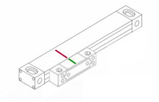
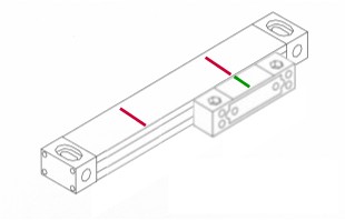
The first task will be to
mark the scales in a way that would visually warn us if the readhead is nearing
the extreme end of the scale. The arm between the trolley and the readhead is
delicate, and if the scale is forcefully run into the end of the scale, it will
break.
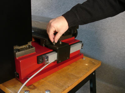
First, remove the two
screws holding the blue plastic piece to the scale body:
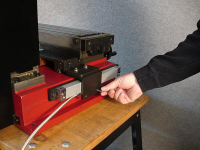
Now, run the trolley back
and forth along the scale with the 'blue plastic piece' still attached to the
trolley. Notice the movement should be smooth and unrestricted. Move the trolley
to the extreme end of the scale until it 'bottoms out' or hits the end. Don't
worry, as long as the readhead is not forcefully struck against the end of the
scale, it will not be damaged. Make a mark from the trolley to the scale body.
Exactly where is not important, but most folks choose to mark from the center of
the trolley as we did.
The Threaded Holes
When
installing scales, the most important thing to remember is that there is not
?one right way?. When faced with the task of mounting scales, it is very
common for different machinists to come up with several different mounting
plans, depending upon their experience, time allowed for installation, and
individual creativity. Remember, installation is more about creativity than
it is an exact science. Which direction you mount the scales, or which holes
you use, depends entirely on what you believe best fits your particular
circumstances. The scale endcaps have two holes, neither of which are
threaded. The larger, oblong holes allow a 6mm bolt to pass through it,
while the smaller round hole is clearanced for a 5mm bolt. The trolley has
two pass-through side holes which are tapped with an M5 x .8 thread. The 4
smaller holes are blind holes, and are tapped with an M4 x .7 thread.
Click on
the following image to view the Scale Hole Sizes and Threaded
Dimensions:
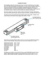
Nuts & Bolts
Depending on your particular kit (i.e. lathe vs. mill, 2 vs. 3 axis etc),
your DRO kit will contain a mixture of metric hardware. These are the most
common size components in our kits:
Socket
head cap screw M6 - 1.0 x 30
Socket
head cap screw M6 - 1.0 x 25
Socket
head cap screw M5 - .8 x 30
Socket
head cap screw M5 - .8 x 10
Lock
washer M6
Lock
washer M5
Flat
washer M6
Flat
washer M5
Hex
nut M6 - 1.0
For
tapping your machine, we recommend having a couple of M6 & M5 plug taps on
hand:
ENCO
(1-800-873-3626) has M5x0.8 plug taps for $3.29 each as part number 311-4141
ENCO
(1-800-873-3626) has M6x1.0 plug taps for $3.76 each as part number 311-4181
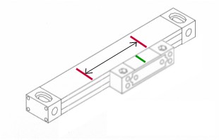
Prepping the Scale
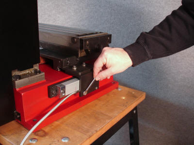
Next, move the trolley to
other extreme end of the scale. Note the marks now 'split'.
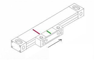
Once the trolley is
bottomed out against the opposite end, make another mark on the scale body
opposite the mark on the trolley.
It should now look like
this:
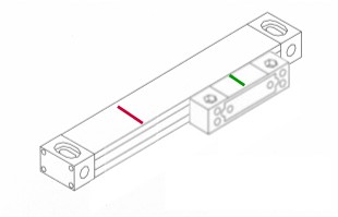
The point of this exercise
is that you now have a visual backup of when the trolley would physically hit
the end of the scale. After properly mounting your scales, the green mark should
always stay between the red marks at all times as in the following illustration:
It is best to mount the
scale body first. After choosing a flat surface, drill and tap the appropriate
size holes. Bolt both ends of the scale into place, leaving one end just loose
enough that it can be 'tapped' into parallel. Run a dial indicator along the top
surface of the scale, making sure the scale does not rise or fall as the machine
moves. THIS IS IMPORTANT. Make sure the scale is true BEFORE you mount the
readhead/trolley assembly.
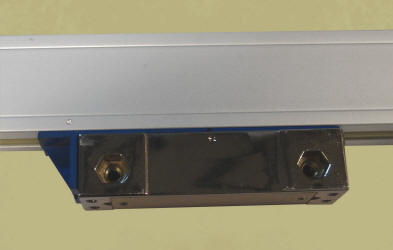
Next, mount the trolley.
It is important to obtain just the right distance or spacing between the
underside of the scale and the trolley. This is where the 'blue plastic piece'
comes in handy. If you mount the trolley such that the blue plastic piece is
snug under the trolley, the spacing will be perfect.
Note the following picture
where the 'blue plastic piece' is snugly between the trolley and the body of the
scale:
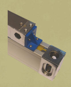
Inside the scale, this is
what the readhead looks like when the scale is properly mounted:
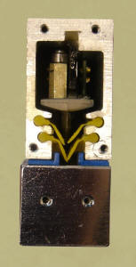 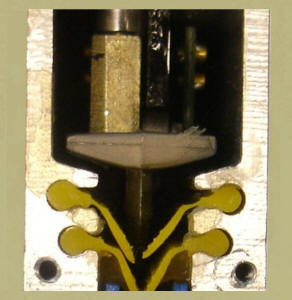
Note the underside of the
readhead is not touching or 'bottoming out' on the inside of the scale body.
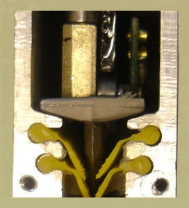
The following pictures
illustrate an IMPROPERLY mounted scale where the 'blue plastic piece' is left
loose between the trolley and the body of the scale:
Inside the scale, the
underside of the readhead is physically dragging along the length of the scale
body. Physical failure of the scale will occur almost immediately as the
readhead will be physically deformed as it drags the underside of the scale:
Dragging the Scale
Now while we say the blue
plastic piece needs to be snug, don't make it too tight. The clearances are
great enough here that you really do not need to 'mic it out'. Mount the trolley
with the 'blue plastic piece' snug and all will be fine. If you look at the
above left photo you can clearly see the blue plastic piece is not even close to
snug, it's simply laying there and would easily slide out if the scale were
tilted to the side. The point here is that there is plenty of room built into
the scale for movement and to not get too wrapped up with this. The only real
catch here is to make sure the scale body is parallel to the machines movement,
and make sure to mount the trolley so that it doesn't run into the end of the
scale.
Note also that most
trolleys are a bit wider than the scale on one side, meaning that if you were to
mount the scale against a perfectly flat surface, the trolley would be pushed
out of alignment. Note in the following picture how the trolley is wider on the
left side of the scale than it is the right. If the scale were forcefully
mounted against a flat surface on the left, the trolley would be forced out of
alignment or pushed well to the right. Forcefully pushing the trolley out of
position will decrease its' life expectancy greatly!
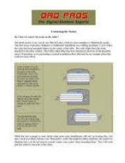 Do
I have to center the scale on the table? Do
I have to center the scale on the table?
The short answer is no,
you do not. But let's take a look at some examples to illustrate the point. The
first series of pictures illustrates a 'traditional' installation on a milling
machines' X axis where the scale has been mounted relative to the
center of the table. The scale (light blue) has been attached to the table
(white). The trolley (dark blue) has been fastened to the base of the machine
(grey). Remember, we're presenting a typical installation first, followed by an
example where the scale has been offset.
|
|
In this
example, the scale body has been mounted on the center of the table.
Traditionally, this is how most scales are mounted.
Note how the trolley (dark blue) is 'centered' on the scale with the
table in the middle, or neutral, position. |
 |
|
|
In this
diagram, the table has been moved to the extreme left. Note the
trolley is nearing the right end of the scale.
|
|
|
Now the table
has been moved to the extreme right most position. Note how the
trolley is nearing, but not over, the left end of the scale. |
|
|
|
|
|
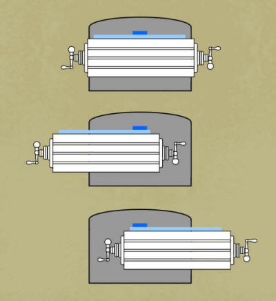
While the last
example is most likely what most scale installations
will end up looking like, let's take a look at a rather extreme
case. Remember, while this might be rather academic, the point is to
illustrate how you do not need to exactly 'center your
scales' when mounting them. They will work just fine offset to one
side or the other. |
|
|
In this
example, the scale body has been mounted well offset to the left of
the table. Note how the trolley is 'centered' relative to the
scale with the table in the middle, or neutral, position. |
 |
|
|
In this
diagram, the table has been moved to the extreme left. Note the
trolley is nearing the right end of the scale.
|
|
|
Now the table
has been moved to the extreme right most position. Again, note how
the trolley is nearing, but not over, the left end of the scale. |
|
Now we realize
no-one is going to mount a scale quite to the extremes of our
previous example. But what we're trying to illustrate is this:
First, you do not need to take elaborate steps trying to ensure a
scale is perfectly 'centered', because it really doesn't matter.
What really does matter is this - wherever you do end up mounting
your scale (centered or not), make sure the trolley is
centered to the scales travel, and doesn't run off the end.
As easy as that! |
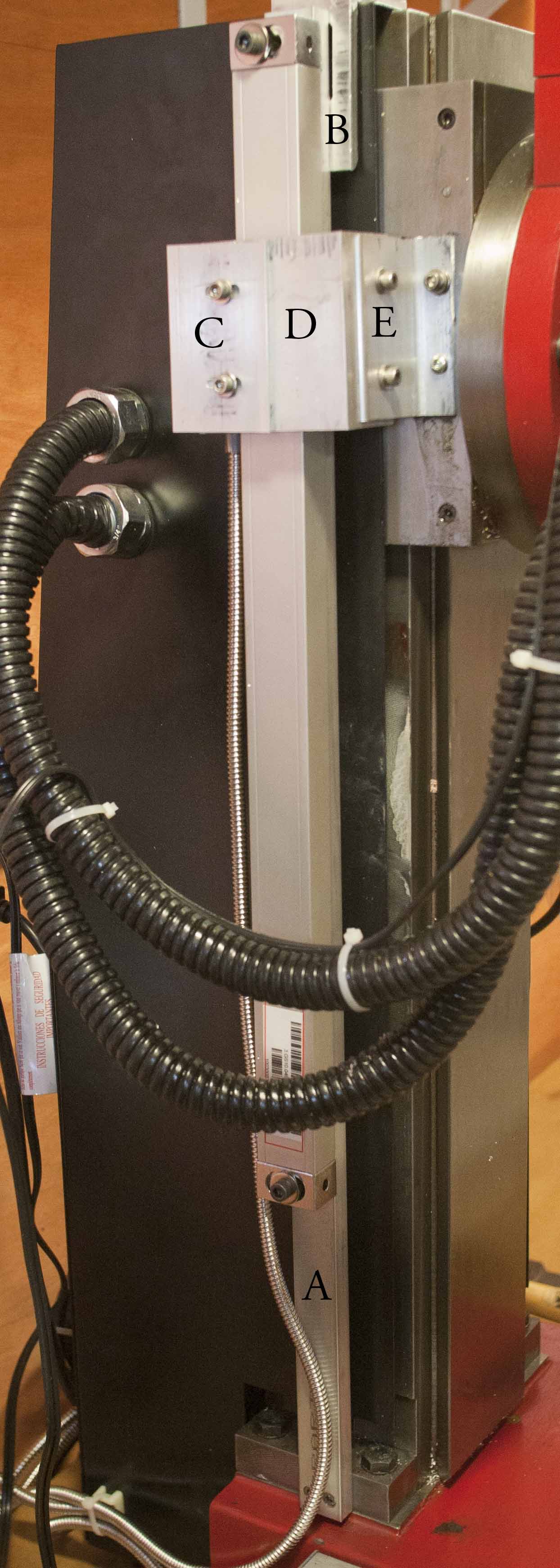
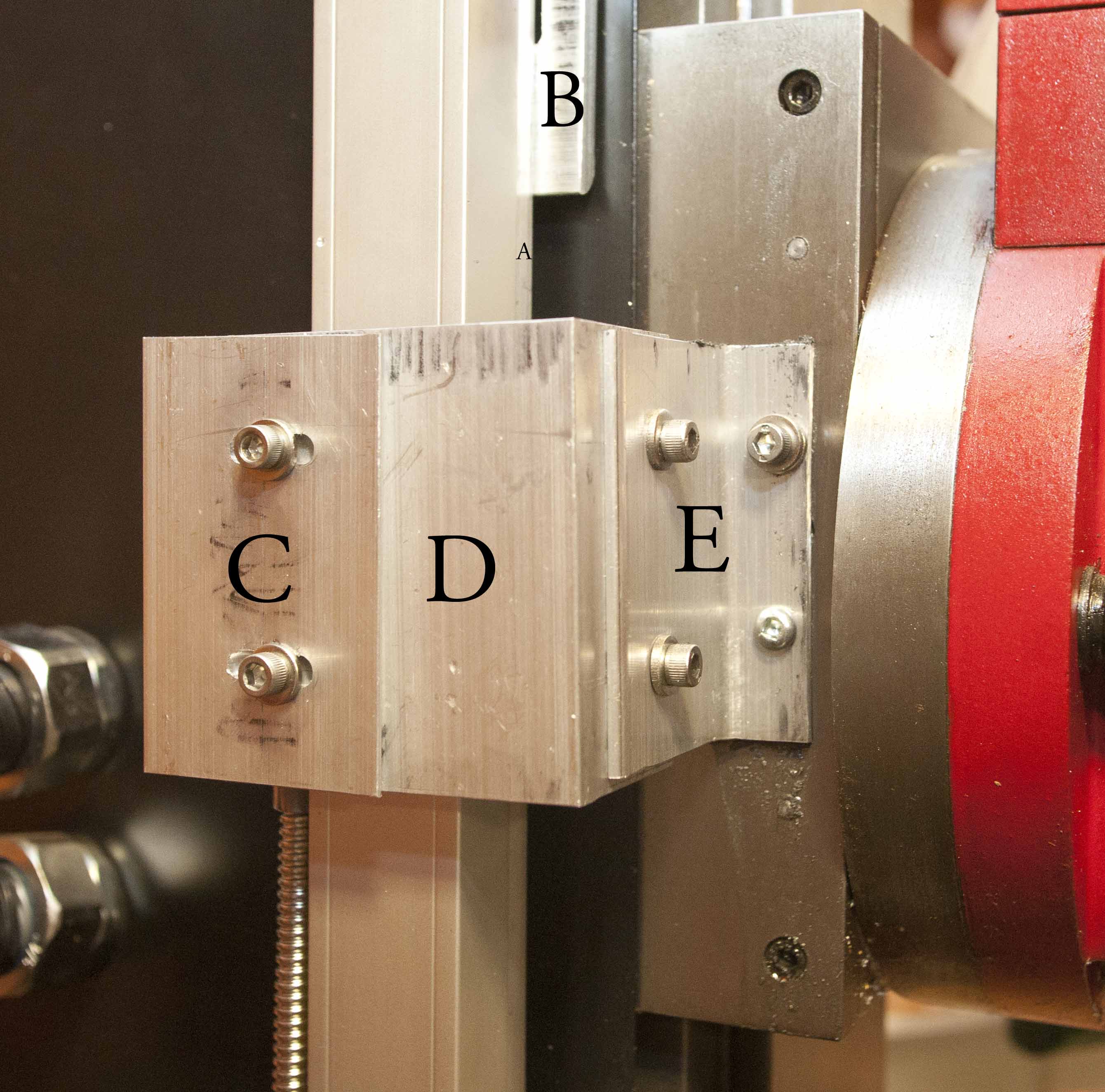
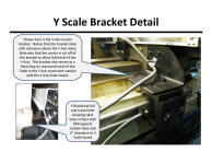
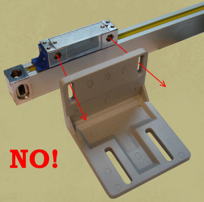
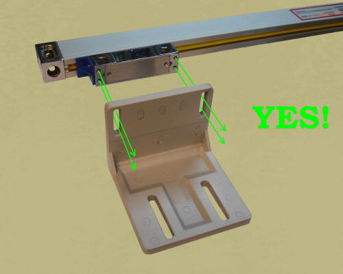
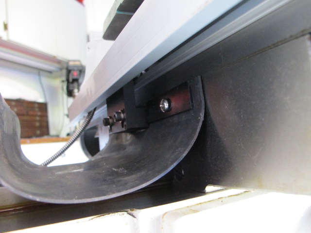
MILL INSTALLATION
For some reason it is
extremely common to try and align the mill brackets with the two large hexagonal
openings on the side of the trolley. The brackets are designed, however, to
align with the four tapped holes on the underside of the trolley, not the
two hexagonal shaped holes on the side. Of course, if it makes better sense to
secure the trolley via the side holes, then go ahead and do it. Modifications
are encouraged! Take a look at the following pictures:
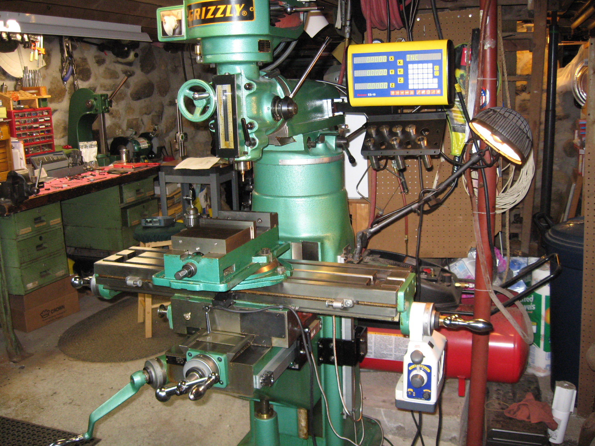
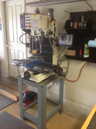
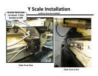
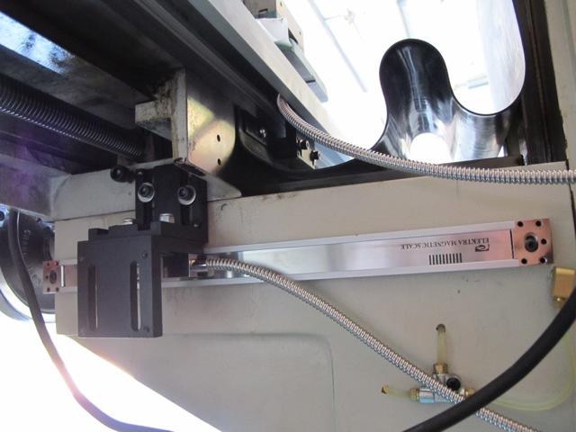
While your particular mill
may look altogether different, the basic concepts remain the same. The first
step is to determine which scale to mount first, and where to mount it. Today,
we've decided to mount the Y scale first as the X scale will pass over the top
of the Y scale. Looking at the right side of our machine, we see that the gib
adjusting screws and table lock mechanism would present a challenge to mounting
a scale on the right side:
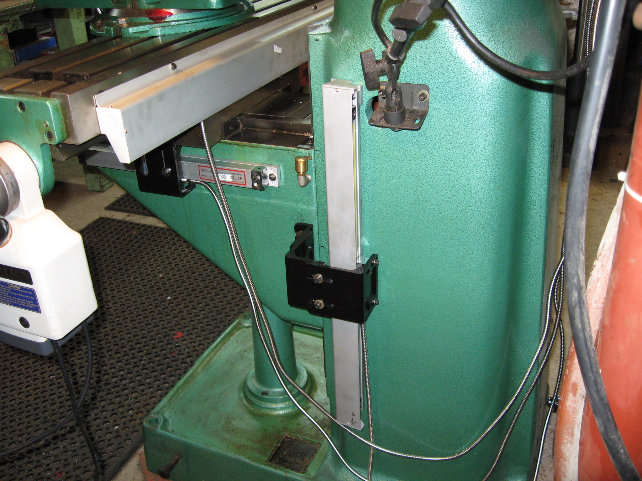
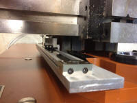
In contrast, the left side
of the mill is relatively unobstructed, making it ideal for mounting the scale:
But while the area is
relatively unobstructed, the side is not machined square:
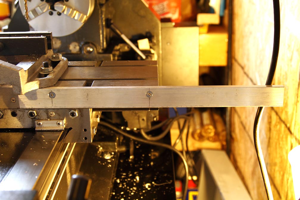
To compensate for the
sloped surface, we'll install a backer bar. On either end of the bar, top and
bottom, are grub screws. These screw in or out, as needed, to level the bar:
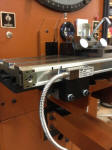
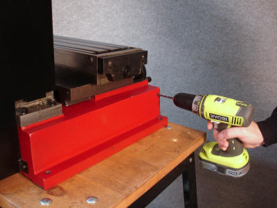
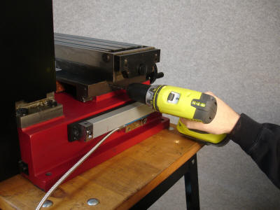
Mark and drill the
mounting holes for the backer bar:
Attach the backer bar
using the supplied bolts:
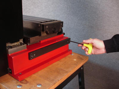
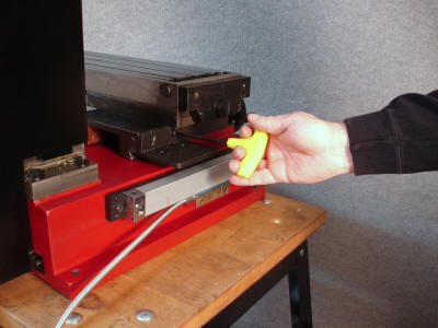
Insert the grub screws on
the backer bar:
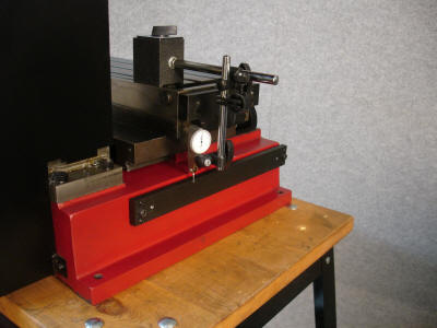
With a dial indicator,
ensure the backer bar is square and perpendicular to the machine slides:
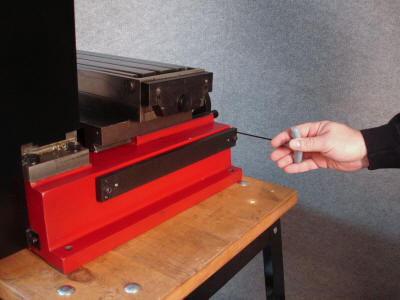
Adjust the grub screws as
needed until the backer bar is square and perpendicular to the machine slides.
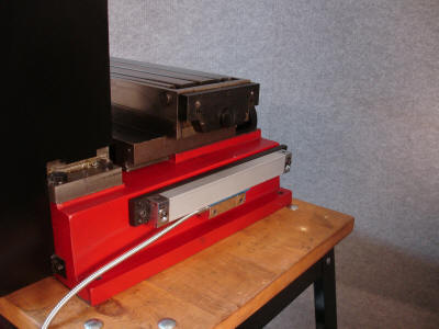
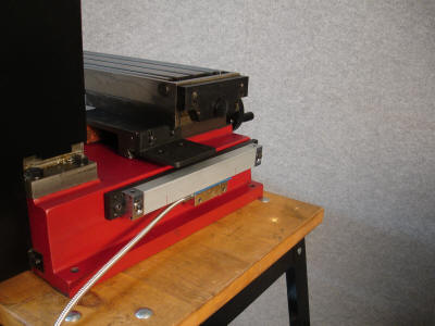
The backer bar is now
installed; level and parallel with the movement of the table:
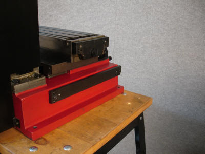
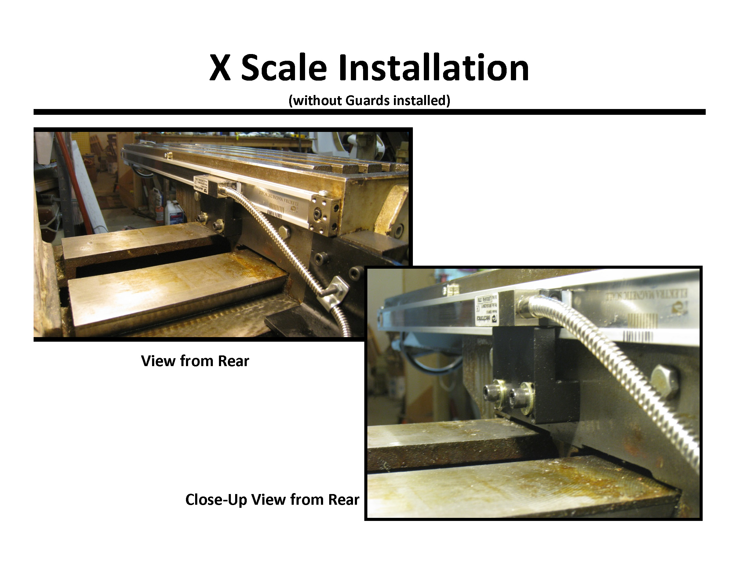
Next, fasten the scale to
the backer bar:
The scale is now
installed!
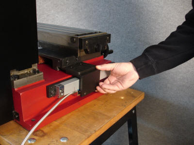
Next, we'll ensure our
scale is parallel with our work surface. First, make sure the mill table is
brought all the way to the rear. Install a dial indicator so that the indicator
tip rests against the top of the scale:
Now move the table to the
front of the machine:
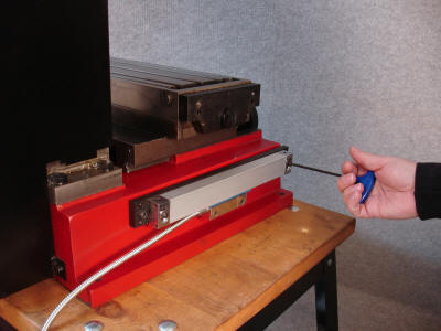
If there is any movement
of the dial indicator, loosen and adjust the scale end bolt as needed. Repeat
until the scale is perfectly aligned.
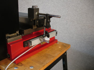
Next, we need to mark the
scales in a way that would visually warn us if the readhead is nearing the
extreme end of the scale. If you have not done this already, here's how to do
it:
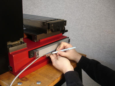
Make a mark from the
trolley to the scale body. Exactly where is not important, but most folks choose
to mark from the center of the trolley as we did.
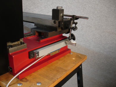
Next, move the trolley to
the end of the scale:

Mark the end of the scale
above the mark on the trolley:
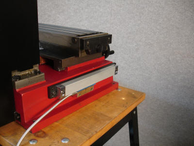
Next, move the trolley to
other extreme end of the scale. Note the marks now 'split':
With the trolley touching
the opposite end of the scale, make another mark on the scale body opposite the
mark on the trolley.
The point of this exercise
is that you now have a visual backup of when the trolley would physically hit
the end of the scale. After properly mounting your scales, the green mark should
always stay between the red marks at all times:

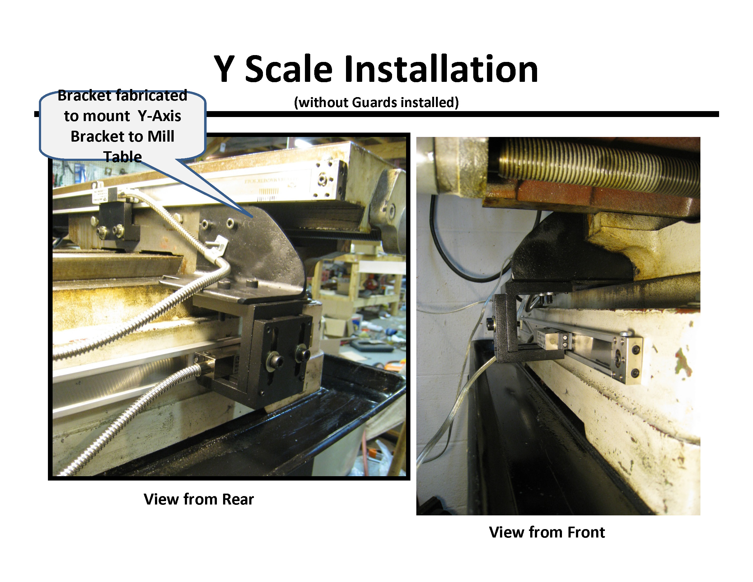
Now place the trolley
bracket against the saddle where you intend to mount it:
Drill the mounting holes
for the trolley bracket:
Now fasten the bracket
against the saddle:
The first trolley bracket
is now installed!
Next, place the second
trolley bracket in place:
Loosely fasten the
two bracket bolts:
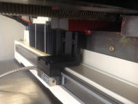
Insert the trolley bolts
through the bracket, into the trolley carriage:
Tighten the trolley bolts.
Make sure the trolley is not twisted as the bolts are tightened.
Adjust the bracket as needed:
Now tighten the bracket
bolts. Again,
make sure the trolley is not twisted as the bolts are tightened.
Adjust the bracket as needed:
All that remains now is to
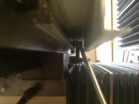
verify the scale runs true with the proper spacing:
Run the table to the back
of the machine:
As you move the table to
the rear, make sure to check the spacing of the blue plastic piece. It should be
snug, but not overly tight, not overly loose. Optimally, it should look like
this:
At no point should the
blue plastic piece bind or become loose. A misaligned scale will look like this:
Note the gap between the
blue plastic piece and the scale body. It is imperative to keep the blue plastic
piece snug along the full travel of the scale. Please refer to the Getting
Familiar with the Scales - Parts and Pieces section for more information
regarding this issue.
If the blue plastic piece
indicates the scale is out of alignment, loosen the scale end bolt and adjust
the scale as needed:
Next, run the trolley to
the other end of the scale. Again, check the blue plastic piece alignment both
during and after the trolley is moved. Loosen and adjust the scale end height as
needed:
Congratulations, the scale
is installed - now don't forget to remove the blue plastic piece!
Scale "Read
Direction"
It makes no difference
which way the scale initially reads. Scale 'read direction' can be easily
changed in the parameters menu after installation. Mount the scale in the
position / direction which makes the most sense. In most cases, mount the scale
with the cable exiting to the rear of the machine, away from the cutter. Please
keep in mind every installation is unique, so there is no one "correct way" to
mount scales. Referencing the Customer installation photos provided above may
help immensely by seeing how our other Customers chose to mount their scales.
For general reference, we
provide the following diagram. Remember, scale read direction is, in the end, a
matter of personal choice:
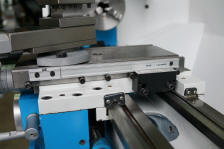
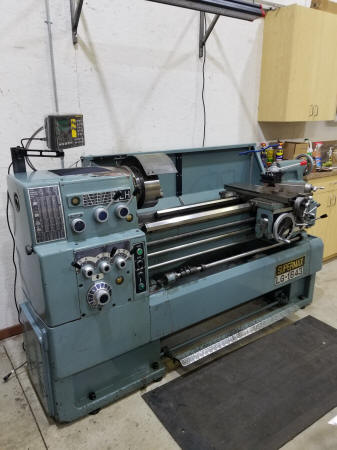
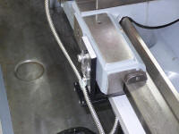
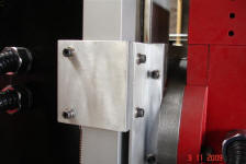
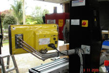
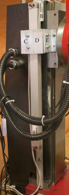
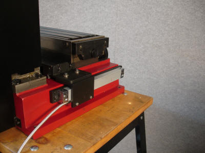
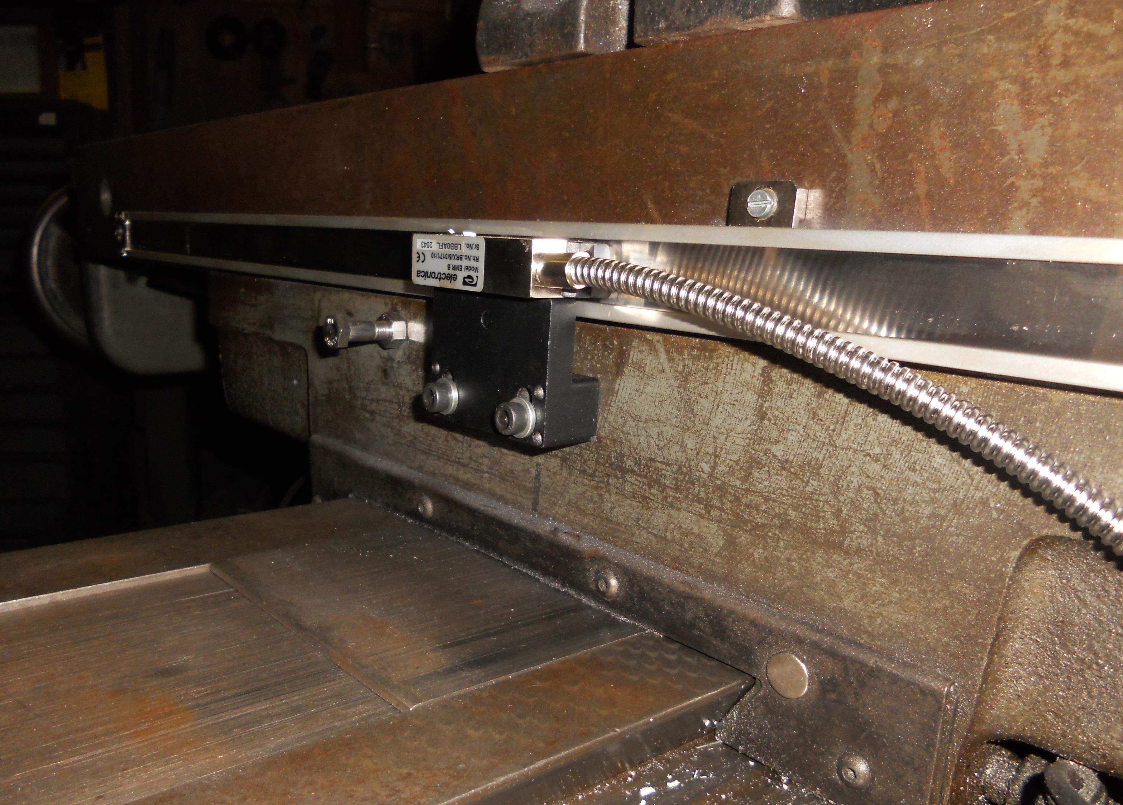
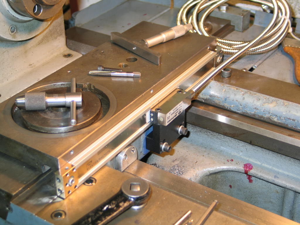
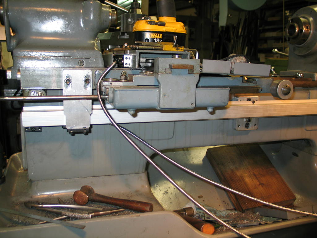
LATHE INSTALLATION
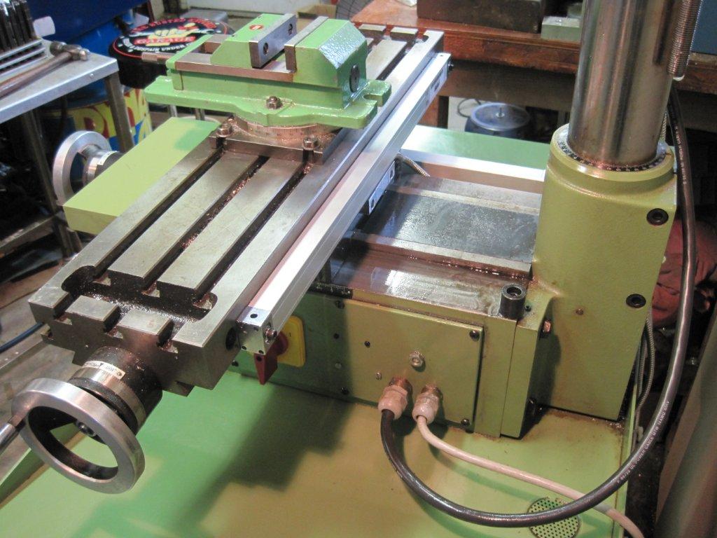
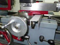
To
install a readout on a lathe the following tips can be used. To mount
the cross slide scale, select a flat surface that is suitable and clear
of the traveling parts of the lathe. The scale should be mounted
insuring that that it is parallel and square to the slide.
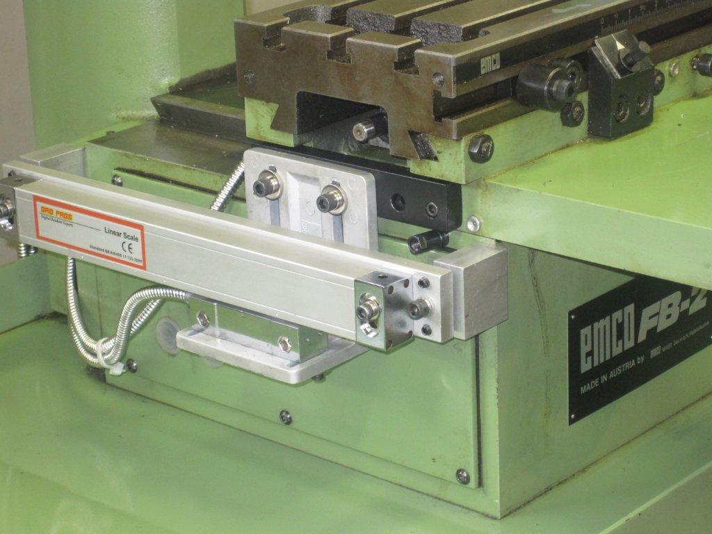
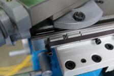
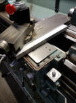
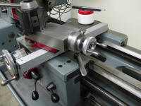
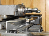
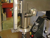
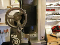
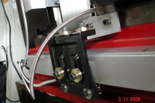
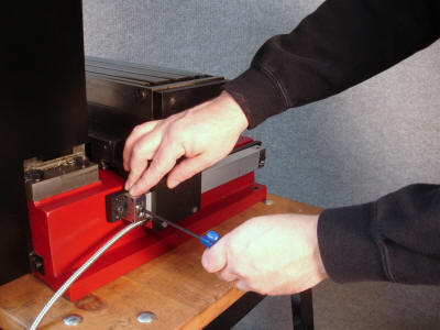
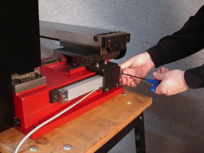
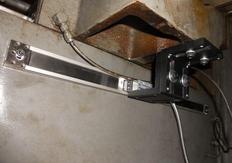
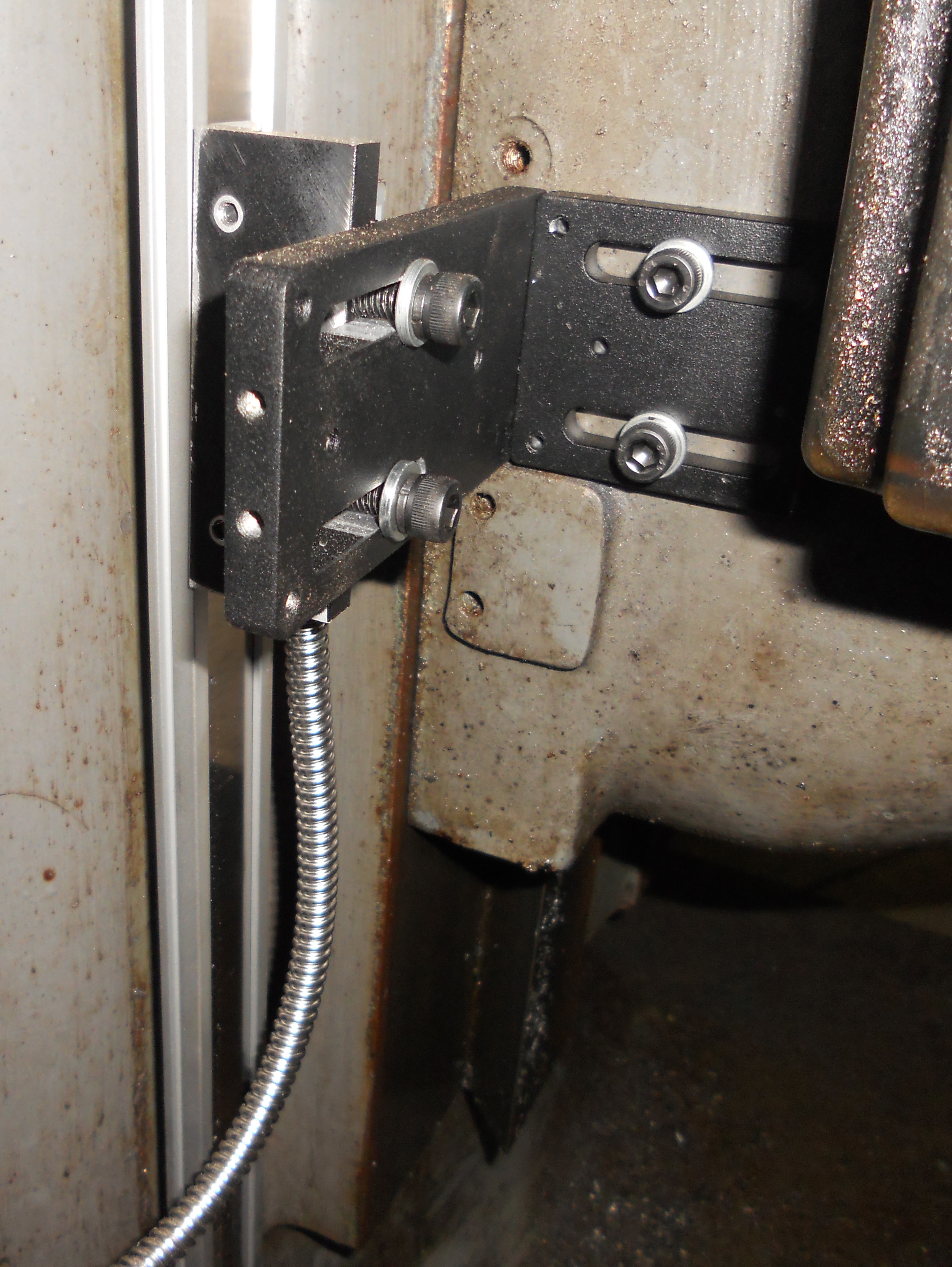
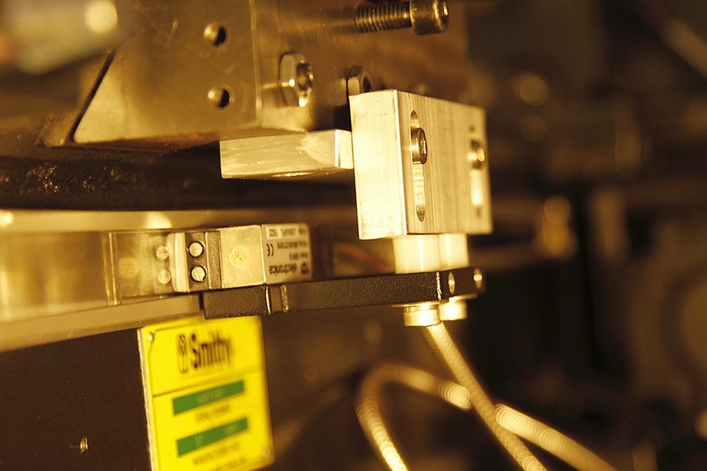
When
mounting the reader head, ensure it travels inline and square to the
scale to avoid any damage to the scale.
Testing for parallel can be done by either a dial indicator or a
precision level.
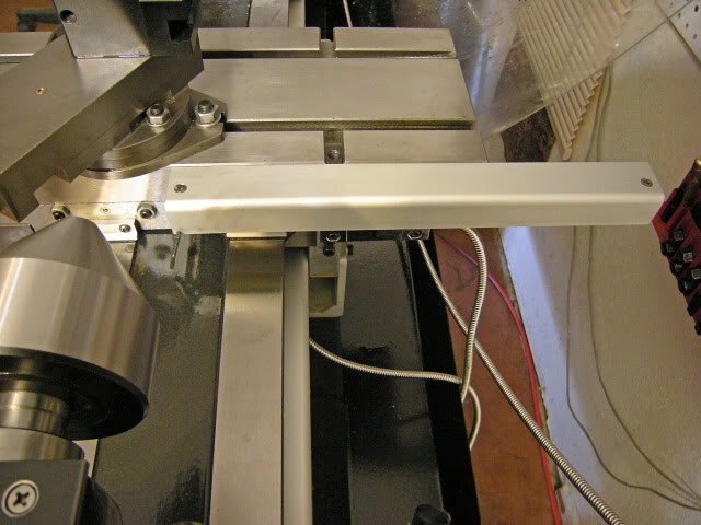
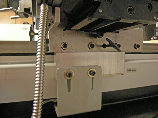
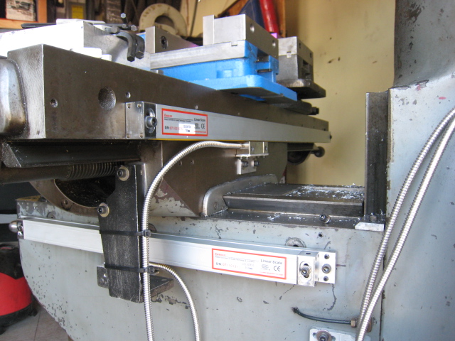
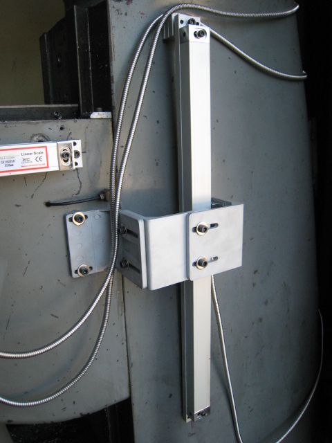
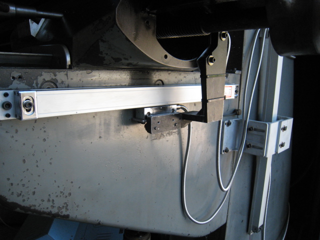
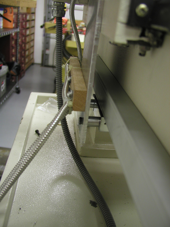
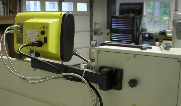
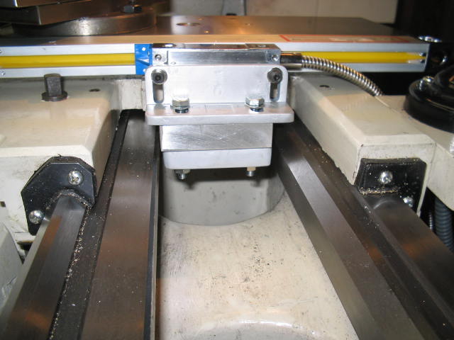
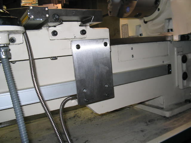
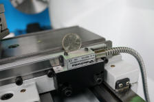
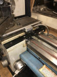
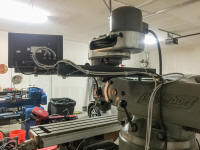
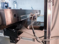
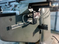
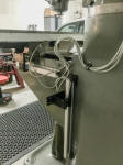
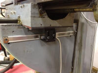
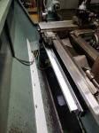
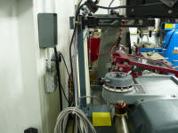
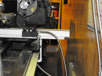
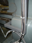
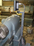
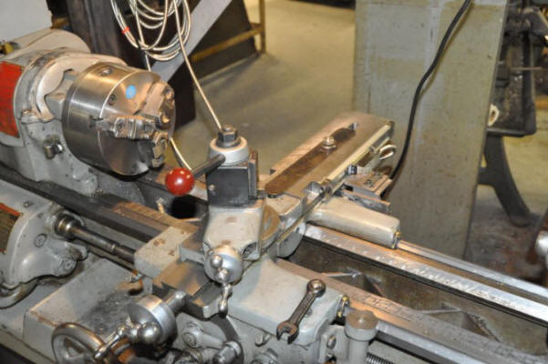
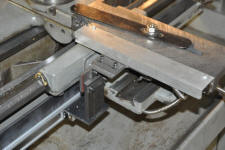
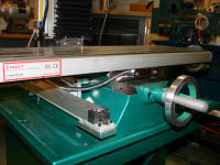
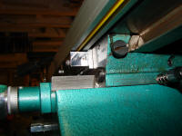
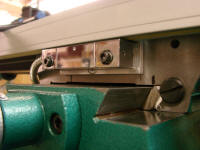
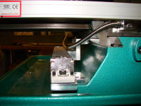
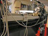
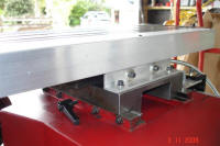
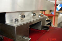
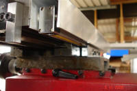
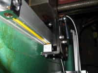
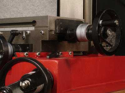
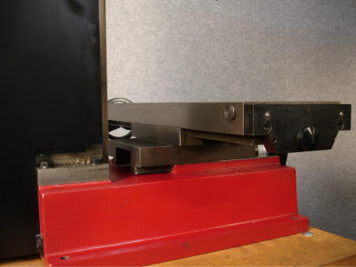
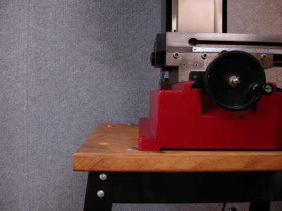
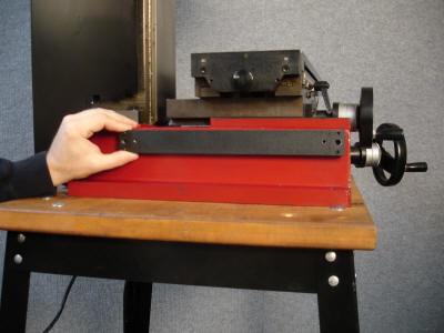
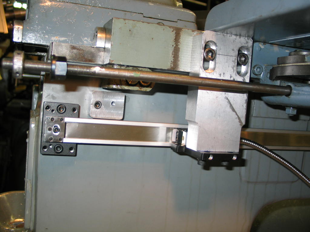
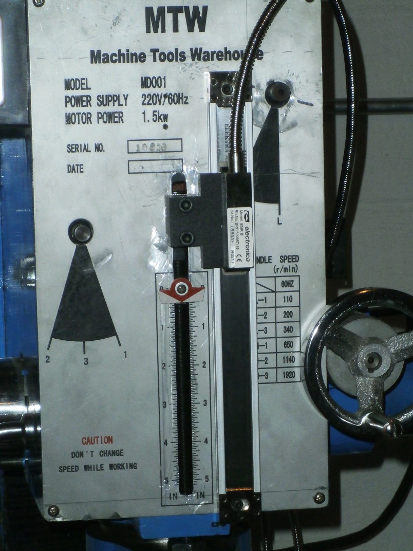
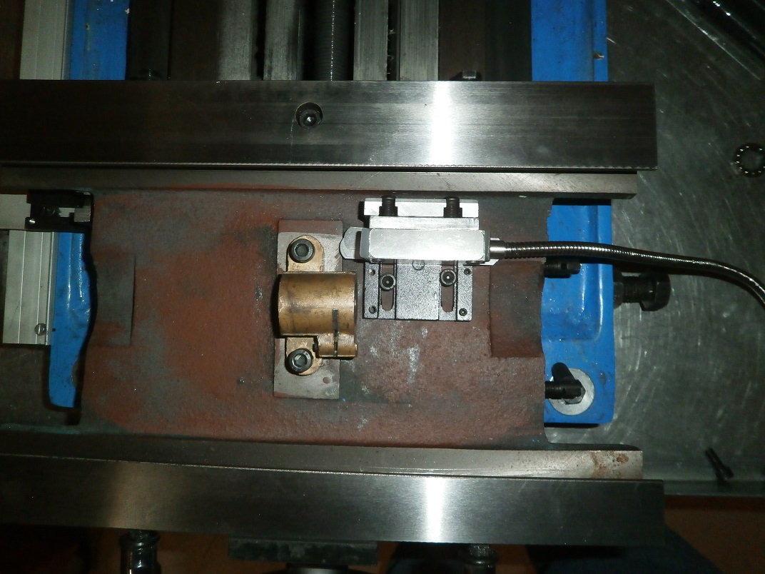
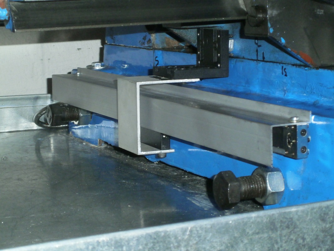
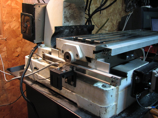
The
longitudinal scale should be mounted on the back of the Lathe (Fig 1)
with the open side of the scale facing down and must be parallel to the
bed. The reader head is mounted to the saddle (Fig. 2 & 3) via the
brackets provided. Some modification may be required for some lathes.
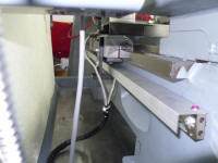
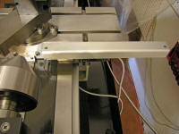
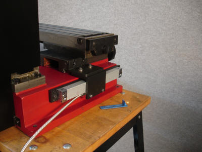
Covers should be mounted over the slides as per Fig.4.
Note: Between the scale
and the reader head there is a blue strip which helps to maintain the correct
distance between the reader head and the scale for installation purposes. This
should be removed after installation.
|


%20(2)n.JPG)